
Engine exhaust side temperature field acquisition method

An acquisition method and engine technology, applied in computer-aided design, image data processing, special data processing applications, etc., can solve problems such as waste of time, manpower, resources and materials, save project cycles, save development costs, and avoid unintended consequences. The effect of rational design

Inactive Publication Date: 2018-05-29
CHERY AUTOMOBILE CO LTD
View PDF3 Cites 2 Cited by
  • Summary
  • Abstract
  • Description
  • Claims
  • Application Information

AI Technical Summary

Problems solved by technology

[0005] In the process of engine design and development, the heat dissipation and temperature rise of the engine can only be checked by making samples, resulting in waste of time, manpower, resources and materials

Method used


Image

  • Engine exhaust side temperature field acquisition method
  • Engine exhaust side temperature field acquisition method
  • Engine exhaust side temperature field acquisition method

Examples


Embodiment Construction

[0054] In order to make the object, technical solution and advantages of the present invention clearer, the implementation manner of the present invention will be further described in detail below in conjunction with the accompanying drawings.

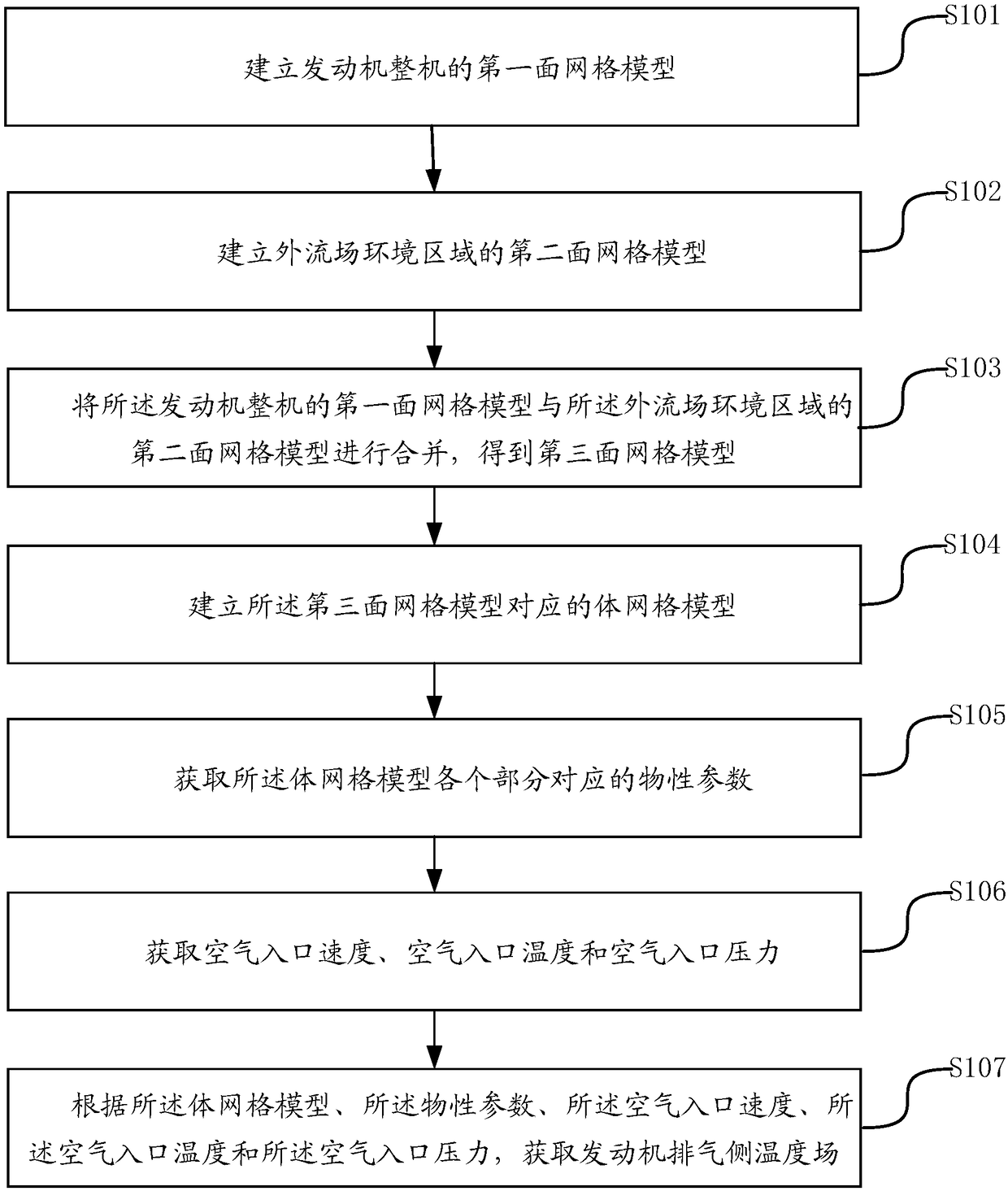
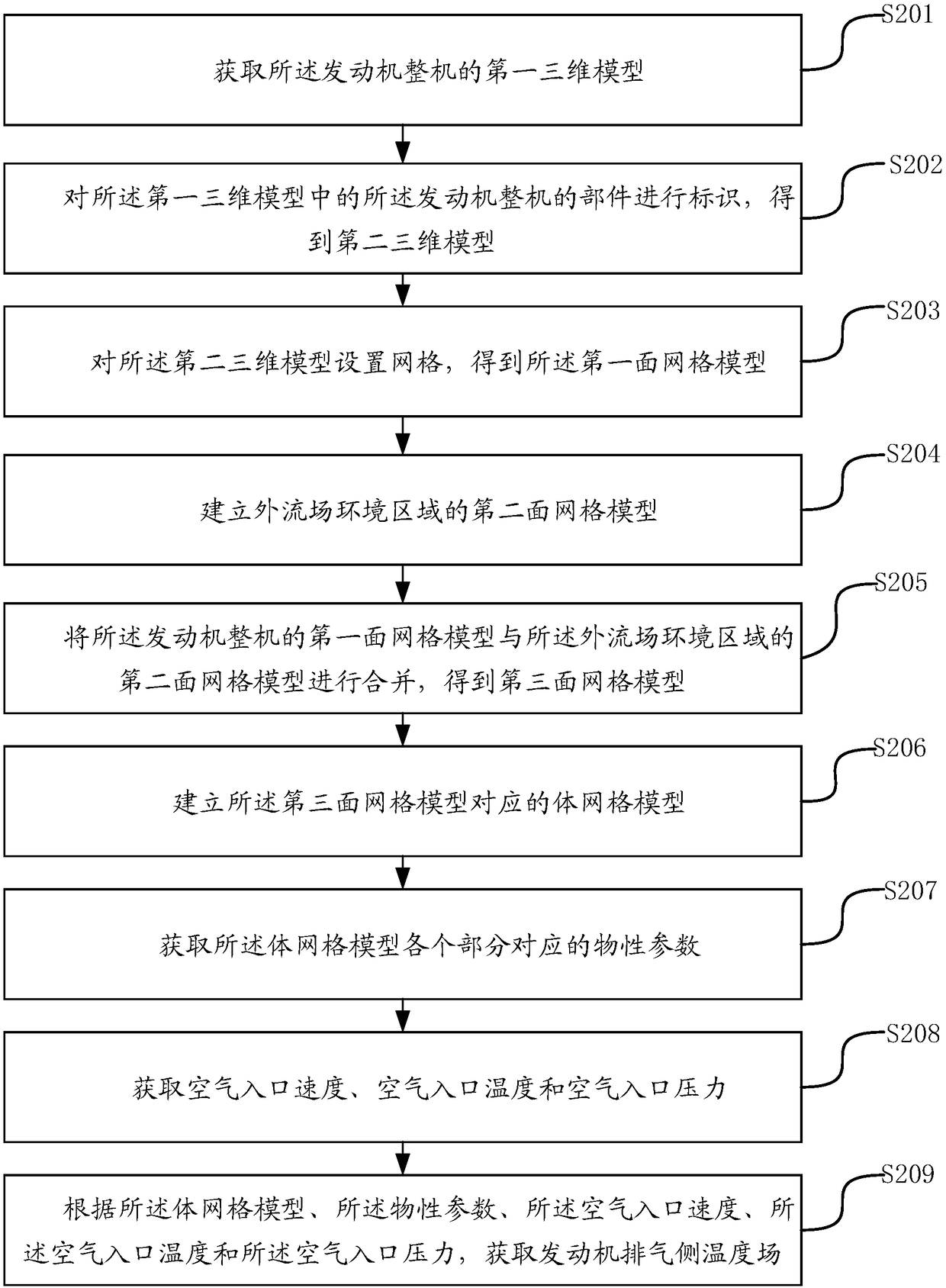
[0055] An exemplary embodiment of the present disclosure provides a method for obtaining the temperature field on the exhaust side of the engine, such as figure 1 As shown, the processing flow of the method may include the following steps:

[0056] Step S101, establishing a first surface mesh model of the complete engine.

[0057] Step S102, establishing a second surface mesh model of the environment area of ​​the external flow field.

[0058] Step S103, combining the first surface mesh model of the complete engine with the second surface mesh model of the external flow field environment area to obtain a third surface mesh model.

[0059] Step S104, establishing a volume mesh model corresponding to the third surface mesh model.

[0...


PUM


Abstract

The invention provides an engine exhaust side temperature field acquisition method. The method comprises establishing a first surface mesh model of an overall engine; establishing a second surface mesh model of external flow field surrounding areas; combining the first surface mesh model of the overall engine and the second surface mesh model of the external flow field surrounding areas to obtaina third surface mesh model; establishing a volume mesh model corresponding to the third surface mesh model; acquiring physical property parameters corresponding to every part of the volume mesh model;acquiring air inlet speed, air inlet temperature and air inlet pressure; according to the volume grid model, the physical property parameters, the air inlet speed, the air inlet temperature and the air inlet pressure, acquiring an engine exhaust side temperature field. By establishing the temperature field model of the overall engine during design and development and acquiring the engine exhaustside temperature field through the temperature field model, the engine exhaust side temperature field acquisition method can help acquire the engine exhaust side temperature field for design and development without manufacturing samples.

Description

technical field [0001] The invention relates to the field of design and development of automobile engines, in particular to a method for obtaining the temperature field at the exhaust side of the engine. Background technique [0002] With the rapid development of engine miniaturization, light weight and compactness, plastic materials are more widely used as engine parts materials, and plastic materials are not as good as metal materials in terms of heat resistance and heat dissipation performance, so the heat dissipation design of the engine is particularly important . [0003] In the prior art, the complete engine includes an engine body and an exhaust system. The engine body includes: a valve chamber cover, a cylinder block, a cylinder head, a frame, an oil pan, a camshaft phase sensor, etc., and the exhaust system includes an exhaust manifold. Tubes, superchargers, pre-catalysts and exhaust tailpipes, etc. During the development of the complete engine, many plastic mate...

Claims


Application Information

Patent Timeline
IPC IPC(8): G06F17/50G06T17/30
CPCG06F30/15G06F30/17G06F2119/08G06T17/30
Inventor 万方方徐亚飞张镇昂亮邢志杰邓晓龙
Owner CHERY AUTOMOBILE CO LTD
Learn More