
Sun-facing light-following solar energy shoe rack with drier

A dryer and solar energy technology, applied in the field of shoe racks, can solve problems such as single function, inconvenience, and inability to dry in time, and achieve the effects of improved utilization, convenient operation, and simple structure

Inactive Publication Date: 2018-05-29
WUXI VOCATIONAL & TECHN COLLEGE
View PDF4 Cites 1 Cited by
  • Summary
  • Abstract
  • Description
  • Claims
  • Application Information

AI Technical Summary

Problems solved by technology

[0002] At present, all kinds of shoe racks on the market have a single function, mainly realizing the function of placing and storing shoes. The traditional way of drying shoes is to put them on the balcony and other sunny places, and people need to dry them according to the weather. For shoes, the drying effect will be very unsatisfactory when encountering rainy weather, and the shoes are very cold when they are just worn in winter, which brings a lot of inconvenience to people's lives; existing shoe racks have certain disadvantages in use , first of all, when encountering rainy and continuous weather, the drying effect will be very unsatisfactory, and it will not be dried in time, which will cause inconvenience. Finally, the strategy of sustainable development requires us to save energy and reduce emissions, and we cannot make better use of resources, which has brought a certain impact on people's use process. Therefore, we propose a sun-following solar shoe rack with a dryer

Method used


Image

  • Sun-facing light-following solar energy shoe rack with drier
  • Sun-facing light-following solar energy shoe rack with drier
  • Sun-facing light-following solar energy shoe rack with drier

Examples


Embodiment Construction

[0017] In order to make the technical means, creative features, goals and effects achieved by the present invention easy to understand, the present invention will be further described below in conjunction with specific embodiments.

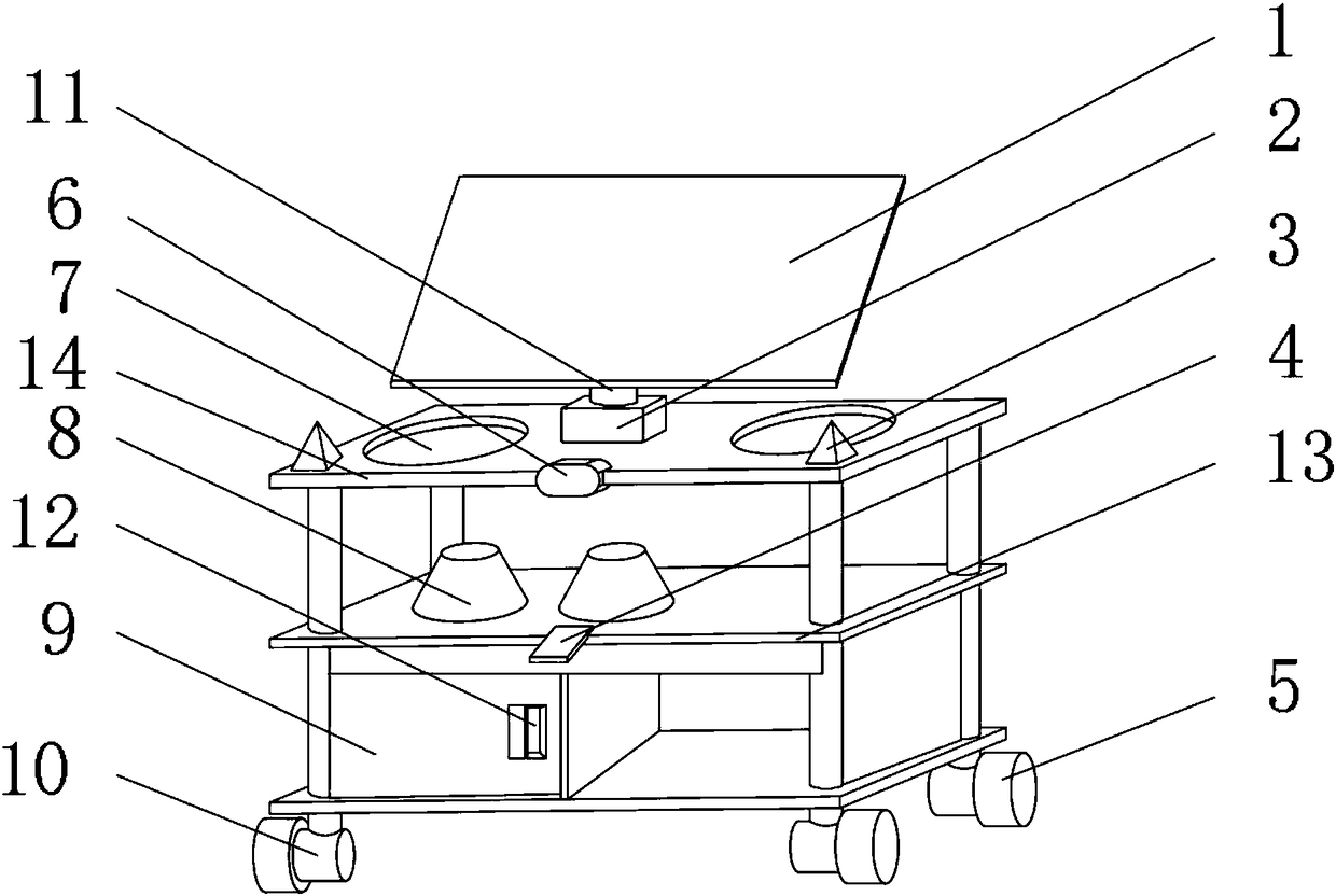
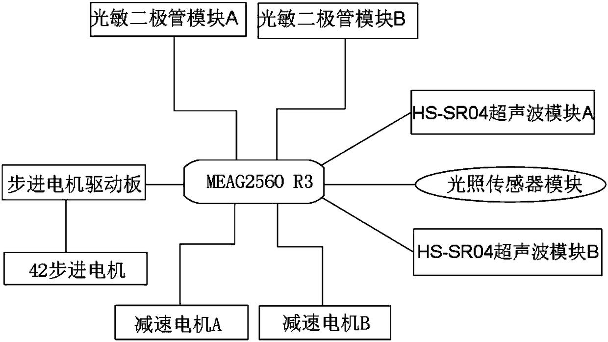
[0018] Such as Figure 1-4 As shown, a sun-following solar shoe rack with a dryer includes a solar panel 1 and a No. 2 baffle plate 13. Seeking the light further improves the utilization rate of solar energy, which is in line with the current concept of energy saving and emission reduction, and can better utilize energy. The outer surface of the bottom end of the support frame 11 is fixedly installed with a stepping motor card slot 2, and the stepping motor card A No. 1 baffle 14 is fixedly installed on the outer surface of the bottom end of the slot 2, and an ultrasonic module card slot 6 is fixedly installed on the front outer surface of the No. 1 baffle 14, and an optical tracking module is fixedly installed on the upper surface of the No. 1 ba...


PUM


Abstract

The invention discloses a sun-facing light-following solar energy shoe rack with a drier. The shoe rack includes a solar panel and a second baffle; the outer surface of the bottom end of the solar panel is fixedly provided with a support frame, the outer surface of the bottom end of the support frame is fixedly provided with a stepping motor clamping groove, the outer surface of the bottom end ofthe stepping motor clamping groove is fixedly provided with a first baffle, the outer surface of the front end of the first baffle is fixedly provided with an ultrasonic module clamping groove, the portion, close to one side, of the upper surface of the first baffle is fixedly provided with a light following module clamping groove, and one side of the light following module clamping groove is provided with a shoe pad tray. The sun-facing light-following solar energy shoe rack with the drier is provided with a drier wind outlet, the light following module clamping groove, the solar panel and alight seeking module clamping groove, the shoe rack can conduct drying in a run of wet weather and the like, and solve the problem that shoes make feet feel ice-cold in winter, in addition, energy conservation and emission reduction can be conducted, and a better use prospect is brought.

Description

technical field [0001] The invention relates to the field of shoe racks, in particular to a sun-following solar shoe rack with a dryer. Background technique [0002] At present, all kinds of shoe racks on the market have a single function, mainly realizing the function of placing and storing shoes. The traditional way of drying shoes is to put them on the balcony and other sunny places. People also need to dry them according to the weather. For shoes, the drying effect will be very unsatisfactory when encountering continuous rainy weather, and the shoes are very cold when they are just worn in winter, which brings a lot of inconvenience to people's lives; existing shoe racks have certain disadvantages in use First of all, when the weather is rainy and continuous, the drying effect will be very unsatisfactory, and it will not be dried in time, which will cause inconvenience. Secondly, the shoes are very cold when they are first worn in winter, which brings a lot of inconvenie...

Claims


Application Information

Patent Timeline
Patent Type & Authority Applications(China)
IPC IPC(8): A47G25/00A47L23/20A47B61/04
CPCA47G25/005A47B61/04A47L23/205
Inventor 丁强陈占富谢欢马华伟崔平
Owner WUXI VOCATIONAL & TECHN COLLEGE
Learn More