Printed board switching test method

A test method and technology for printed boards, applied in the field of testing, can solve problems such as poor practicability, and achieve the effects of good practicability, improved work efficiency, and rapid and accurate judgment.

Inactive Publication Date: 2018-05-25
XIAN KUNLUN IND GRP
View PDF4 Cites 2 Cited by
  • Summary
  • Abstract
  • Description
  • Claims
  • Application Information

AI Technical Summary

Problems solved by technology

[0003] In order to overcome the shortcomings of the poor practicability of the exist

Method used


Image

  • Printed board switching test method
  • Printed board switching test method
  • Printed board switching test method

Examples


Embodiment Construction

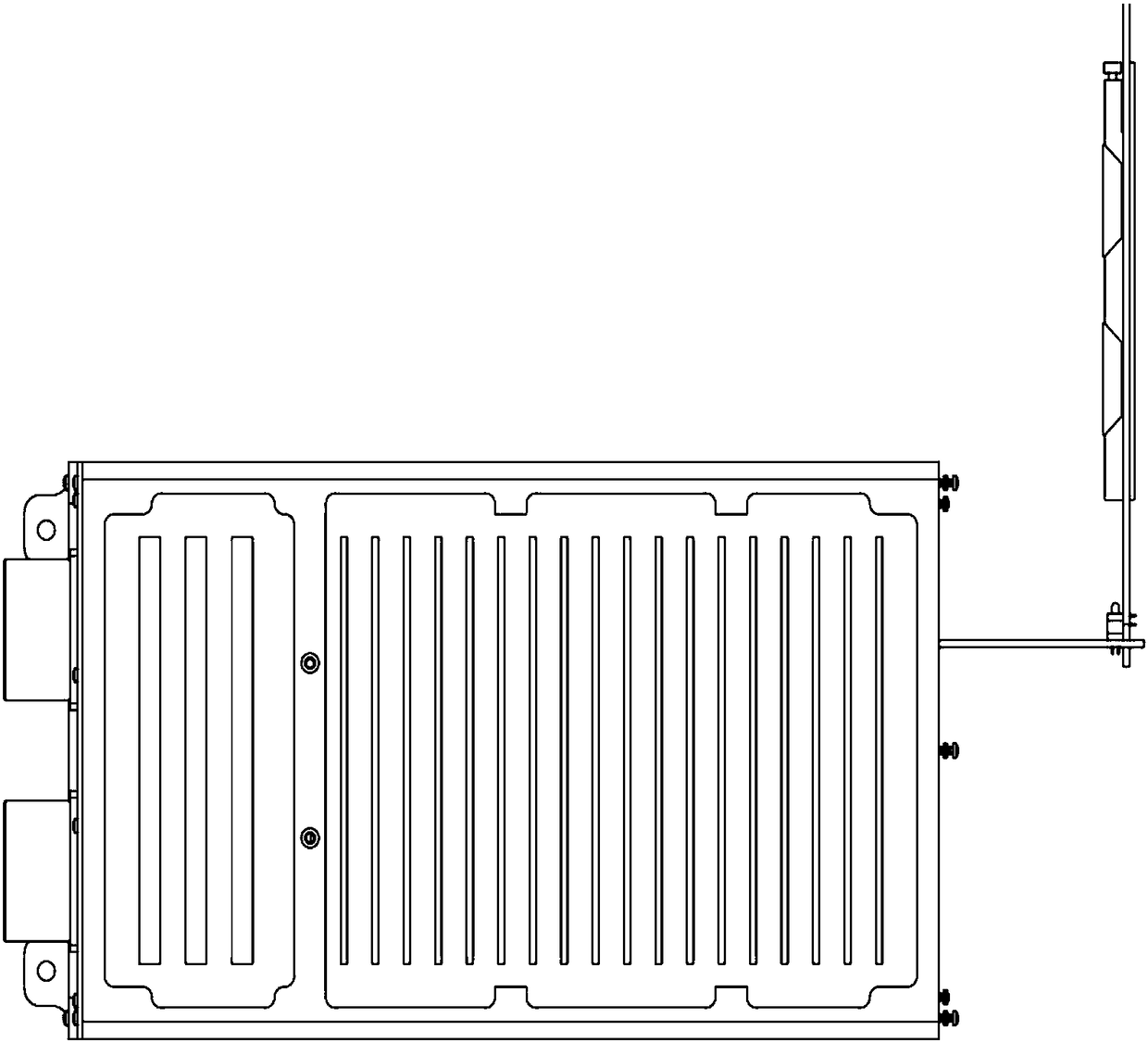
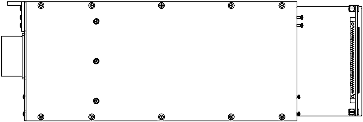
[0016] refer to Figure 1-3 . The specific steps of the printed board transfer test method of the present invention are as follows:

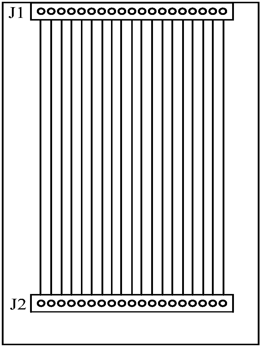
[0017] Design the circuit adapter board, the circuit adapter board extends out of the control box, the two ends of the circuit adapter board are installed with the same type of plug J1 as the printed board to be tested, and the socket J2 that matches the type of the plug J1, and the edge of the plug J1 is in line with the The edges of the adapter board are overlapped, and each core of the plug J1 and the socket J2 of the circuit adapter board is connected by wiring on the component surface or the welding surface of the printed board.

[0018] Use the following steps when using the printed board transfer debugging method:

[0019] Step 1. Ensure that the control box is in the power-off state, and take out the printed board to be tested from the control box;

[0020] Step 2. Refer to figure 2 Insert the plug J1 end of the circuit adapter boar...


PUM


Abstract

The invention discloses a printed board switching test method, which is used for solving the technical problem of poor practicability of an existing test method. The technical scheme is characterizedby, under the power-off state of a control cabinet, taking a printed board to be tested out of the control cabinet; inserting a welding plug end of a circuit switching plate into a slot of the printedboard to be tested in the control cabinet; vertically inserting the printed board to be tested into a socket end of the circuit switching plate outside the control cabinet; and according to test requirements, carrying test on test points on the printed board through test meters and instruments. The printed board to be tested is switched to the outside portion of the control cabinet; and test personnel can use all ports of equipment in a live line manner through test equipment of a universal meter and an oscilloscope and the like to observe whether work state of each component and each signalinput and output state are normal. The printed board switching test method ensures live test of the printed board signal and fast and accurate judgment of fault points of the printed board, prevents secondary failure due to misoperation during measurement of fly line lead-out signals, and is good in practicality.

Description

technical field [0001] The invention relates to a test method, in particular to a printed board transfer test method. Background technique [0002] refer to Figure 4 . In the existing test methods, the space layout of the artillery control reinforcement machine is compact in design, and the core wires of the outlet sockets of the reinforcement chassis cannot cover all the signals that need to be tested. When debugging the reinforced computer or when the computer fails, it is necessary to detect the output signal of the printed board and the status of the components with electricity at this time to determine whether the fault point and the working status of the components are normal. Due to the limited space of the reinforced chassis, it is impossible to directly use test instruments and instruments to test the required test signals. The usual method is: first power off the chassis, take out the printed board to be tested, and place all the test signals on the printed board...

Claims


Application Information

Patent Timeline
IPC IPC(8): G01R31/28
Inventor 王珑吴晓蓓吴鹏展娄超群张君李彬李慧慧燕丽娥高建军黄少保
Owner XIAN KUNLUN IND GRP
Why Eureka
Try Eureka