Expansion joint for highway bridge technical services
A technology for technical services and highway bridges, applied in the field of technical services, can solve the problems of constant comb expansion joints and replacement parts, and achieve the effect of small clearance, easy operation and small vibration
- Summary
- Abstract
- Description
- Claims
- Application Information
AI Technical Summary
Problems solved by technology
Method used
Image
Examples
Embodiment 1
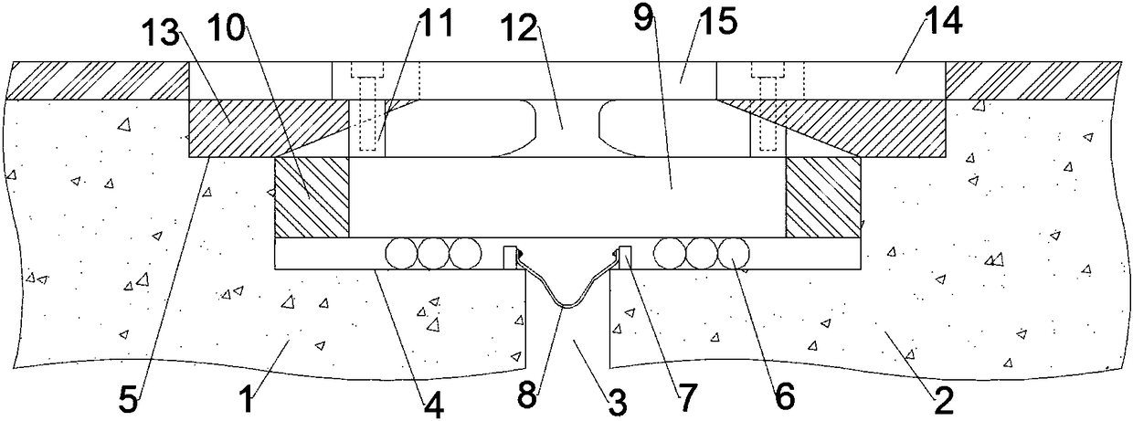
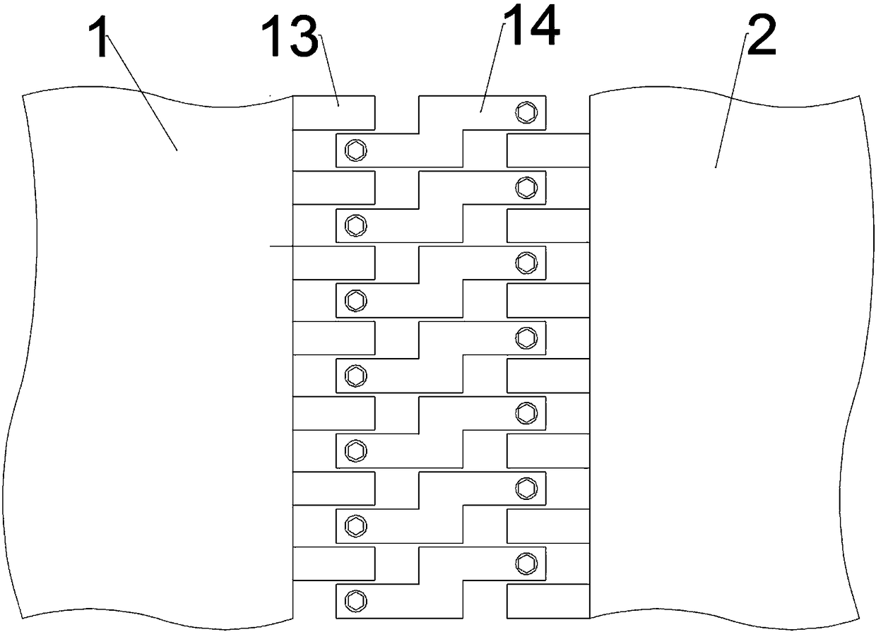
[0018] Embodiment 1: When the expansion joint is used in a highway bridge, an expansion joint for highway bridge technical service includes a first bridge 1, a second bridge 2 and a gap 3, the right end of the first bridge 1 and the left end of the second bridge 2 are The slit 3 is the axis of symmetry and is respectively provided with a first trapezoidal surface 4 and a second trapezoidal surface 5 above the first trapezoidal surface 4. The upper surface of the first trapezoidal surface 4 is provided with three rolling axes 6, and the upper surface of the first trapezoidal surface 4 is Located on the outer side of the gap 3 is fixedly connected with a limit bolt 7 for preventing the rolling shaft 6 from slipping, and a water guide plate 8 is arranged between the gap 3, and the top of the water guide plate 8 is fixedly connected with the limit bolt 7 by bolts, and the rolling shaft 6 A bracket 9 is arranged on the top, between the left side wall of the bracket 9 and the first b...
Embodiment 2
[0021] Embodiment 2: when not in use, an expansion joint for highway bridge technical service, including a first bridge 1, a second bridge 2 and a gap 3, the right end of the first bridge 1 and the left end of the second bridge 2 take the gap 3 as the axis of symmetry respectively A first trapezoidal surface 4 and a second trapezoidal surface 5 located above the first trapezoidal surface 4 are provided. Three rolling shafts 6 are arranged on the upper surface of the first trapezoidal surface 4. The upper surface of the first trapezoidal surface 4 is located outside the gap 3 and its position is fixed. A limit bolt 7 for preventing the rolling shaft 6 from slipping is connected, a water guide plate 8 is arranged between the gaps 3, the tops of the water guide plate 8 are fixedly connected with the limit bolt 7 by bolts, and a bracket 9 is arranged above the rolling shaft 6 , between the left side wall of the bracket 9 and the first bridge 1, between the right side wall of the br...
PUM
 Abstract
Description
Claims
Application Information
 - Generate Ideas
- Intellectual Property
- Life Sciences
- Materials
- Tech Scout
- Unparalleled Data Quality
- Higher Quality Content
- 60% Fewer Hallucinations
Browse by: Latest US Patents, China's latest patents, Technical Efficacy Thesaurus, Application Domain, Technology Topic, Popular Technical Reports.
© 2025 PatSnap. All rights reserved.Legal|Privacy policy|Modern Slavery Act Transparency Statement|Sitemap|About US| Contact US: help@patsnap.com


