Ultralow-temperature fixed ball valve

A fixed, ultra-low temperature technology, applied to valve details, valve devices, shaft seals, etc., can solve problems such as loss of sealing performance, easy blockage of springs, loss of elasticity, etc.

Inactive Publication Date: 2018-05-22
超核阀门有限公司
View PDF8 Cites 0 Cited by
  • Summary
  • Abstract
  • Description
  • Claims
  • Application Information

AI Technical Summary

Problems solved by technology

[0002] Existing ball valves are generally composed of valve body, valve seat, ball, valve stem, and valve cover. The lower end of the valve stem is fixedly connected to the ball. The valve cover and valve body are connected by bolts. O-shaped spring, when there are particles or dust in the pipeline, the spring will be easily blocked, and then lose its elasticity. At the same time, the original valve seat structure uses O-ring for sealing. The type ring hardens and then loses the sealing performance, so we propose an ultra-low temperature fixed ball valve

Method used


Image

  • Ultralow-temperature fixed ball valve
  • Ultralow-temperature fixed ball valve
  • Ultralow-temperature fixed ball valve

Examples


Embodiment Construction

[0017] The following will clearly and completely describe the technical solutions in the embodiments of the present invention with reference to the accompanying drawings in the embodiments of the present invention. Obviously, the described embodiments are only some, not all, embodiments of the present invention.

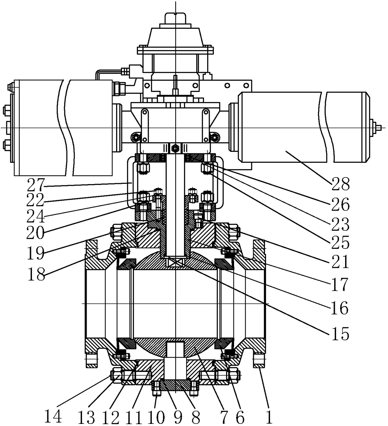
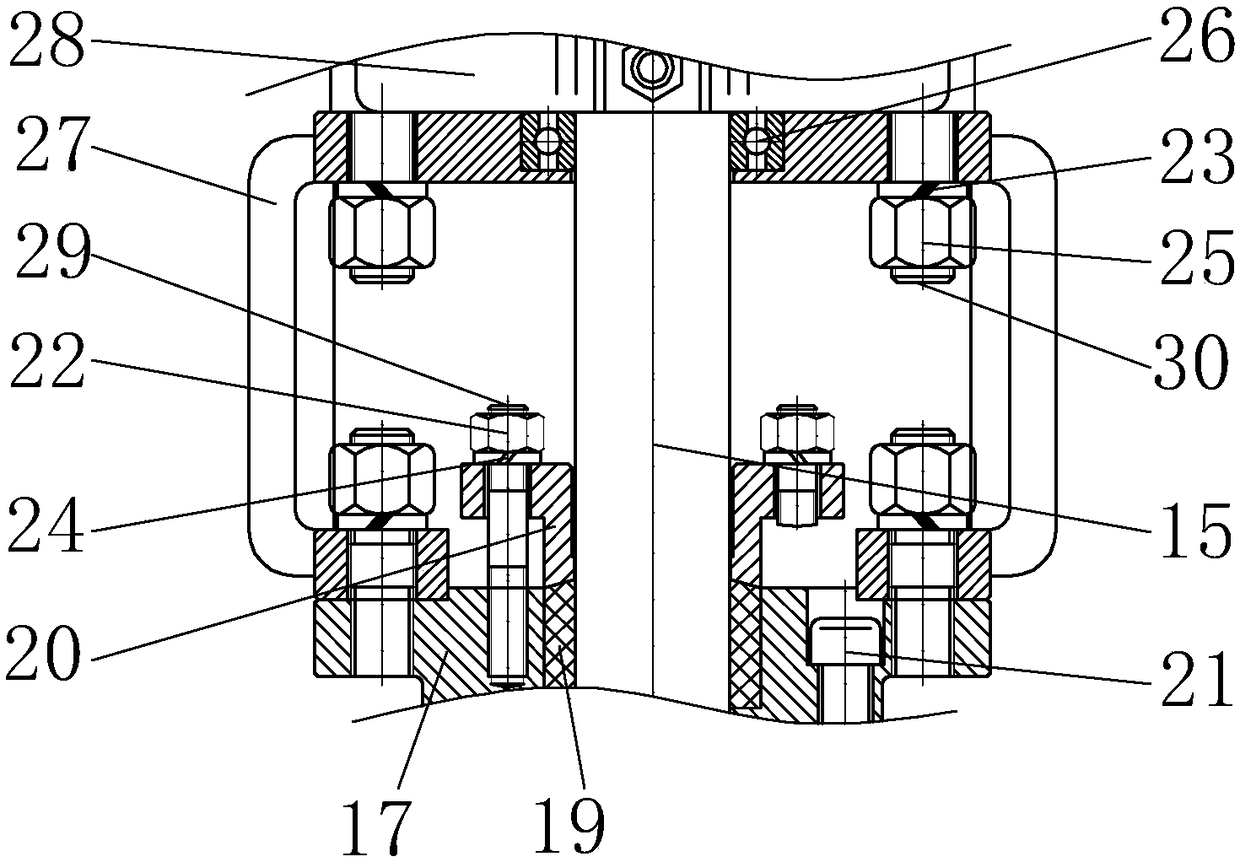
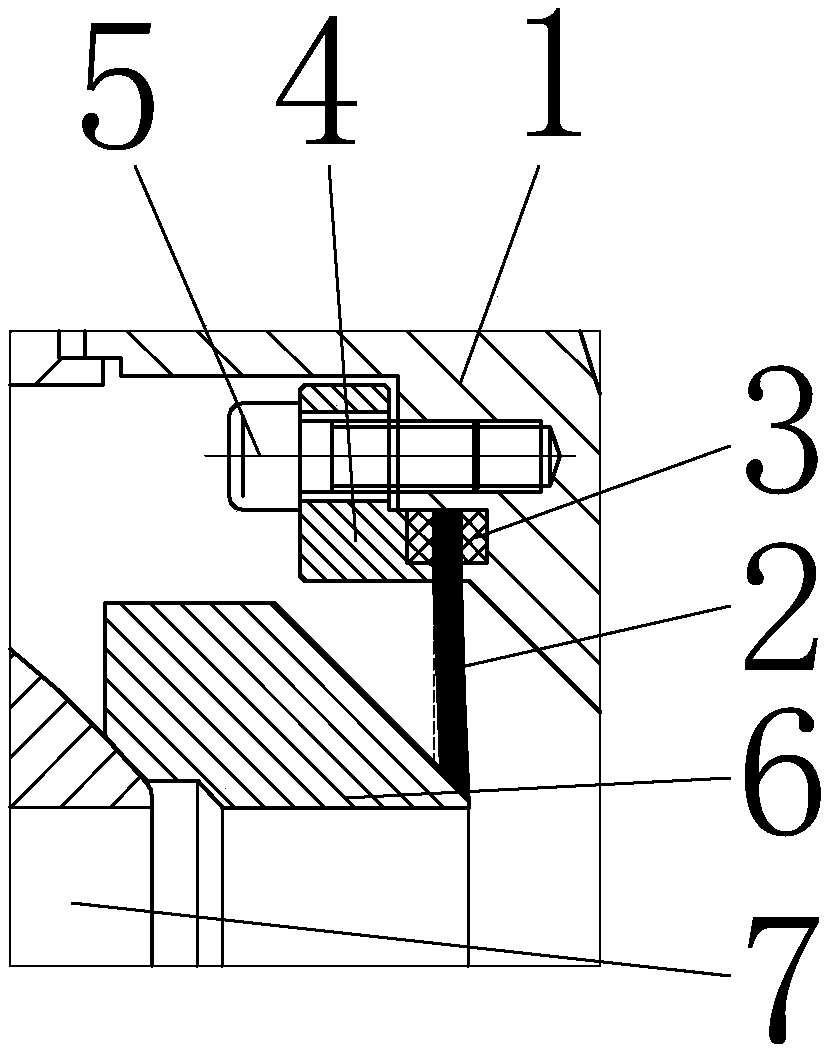
[0018] refer to Figure 1-3 , an ultra-low temperature fixed ball valve, comprising a middle valve body 11, left and right bodies 1 are arranged on both sides of the middle valve body 11, a plurality of first screw rods 14 are equidistantly arranged on the sides of the middle valve body 11, and the first screw rods 14 One end runs through one side of the left and right body 1 and is provided with a first nut 13. A third gasket 12 is provided between the left and right bodies 1 and the middle valve body 11. A first screw rod 14 is provided, and the first screw rod 14 runs through one side of the left and right body 1 and is screwed through the first nut 13 , so that t...


PUM


Abstract

The invention relates to the technical field of valves, in particular to an ultralow-temperature fixed ball valve. The ultralow-temperature fixed ball valve comprises a middle valve body. The two sides of the middle valve body are each provided with a left body and a right body. A ball body is arranged in the middle valve body. Valve seats are arranged on the two sides of the ball body. A plurality of pressing plates are arranged on the inner walls of the left bodies and the right bodies. A pressing plate bolt is arranged on one side of each pressing plate. One end of each pressing plate boltpenetrates through the corresponding pressing plate to be fixedly connected with the inner walls of the corresponding left body and the corresponding right body. Two first washers are arranged betweeneach pressing plate and the corresponding left body and the corresponding right body. The upper end of a bottom valve rod penetrates through the middle valve body to be fixedly connected with the ball body. A packing mechanism is arranged on the upper portion of the middle valve body. A support is arranged on the upper portion of the packing mechanism. An actuator is arranged on the upper portionof the support. An upper valve rod is connected with the bottom of the actuator. The lower end of the actuator sequentially penetrates through the support and the packing mechanism to be arranged inthe ball body. According to the ultralow-temperature fixed ball valve, the situation that springs loss elasticity due to the fact that the springs are completely blocked by particles or dust is avoided, and meanwhile, the overall valve seat structure can still maintain the sealing performance in a low temperature environment,

Description

technical field [0001] The invention relates to the technical field of valves, in particular to an ultra-low temperature fixed ball valve. Background technique [0002] Existing ball valves are generally composed of valve body, valve seat, ball, valve stem, and valve cover. The lower end of the valve stem is fixedly connected to the ball. The valve cover and valve body are connected by bolts. O-shaped spring, when there are particles or dust in the pipeline, the spring will be easily blocked, and then lose its elasticity. At the same time, the original valve seat structure uses O-ring for sealing. The ring hardens and then loses the sealing performance, so we propose an ultra-low temperature fixed ball valve. Contents of the invention [0003] The purpose of the present invention is to solve the shortcomings in the prior art, and propose an ultra-low temperature fixed ball valve. [0004] In order to achieve the above object, the present invention adopts the following te...

Claims


Application Information

Patent Timeline
Patent Type & Authority Applications(China)
IPC IPC(8): F16K5/06F16K5/08F16K5/20F16K41/02
CPCF16K5/0694F16K5/0647F16K5/201
Inventor 张崇彪张维龙
Owner 超核阀门有限公司
Why Eureka
Try Eureka