Improved structure based on detection port of ventilation equipment

A technology of ventilation equipment and detection port, which is applied in the field of improved structure based on the detection port of ventilation equipment, can solve problems such as poor sealing performance, and achieve the effects of avoiding waste, saving costs and overcoming poor sealing performance.

Active Publication Date: 2017-10-27
CHENGDU OLYMVAX BIOPHARM
View PDF7 Cites 0 Cited by
  • Summary
  • Abstract
  • Description
  • Claims
  • Application Information

AI Technical Summary

Problems solved by technology

[0003] The technical problem to be solved by the present invention is to provide an improved structure based on the detection port of the ventilator to overcome the problem of poor sealing of the existing testing device

Method used


Image

  • Improved structure based on detection port of ventilation equipment
  • Improved structure based on detection port of ventilation equipment

Examples


Embodiment 1

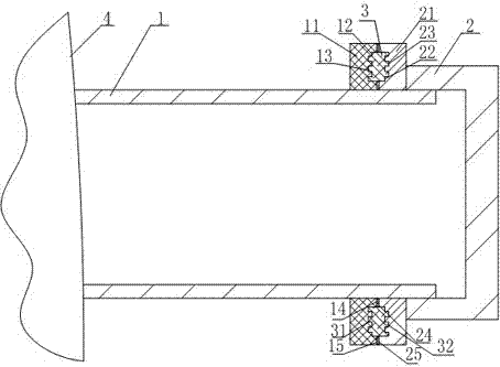
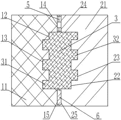
[0019] like figure 1 , figure 2 As shown, based on the improved structure of the detection port of the ventilation device, it includes the detection port 1 arranged on the ventilation device 4, the detection cover 2 matched with the detection port 1, the inner wall of the detection cover 2 is provided with an internal thread, and the width of the internal thread is The outer wall of the detection port 1 is provided with an external thread that cooperates with the internal thread, and the lower end of the external thread on the outer wall of the detection port 1 is provided with an annular bump I11, and the annular bump I11 is recessed inwards. The annular groove I12 matched with the sealing ring 3, three annular grooves III13 are uniformly arranged at the bottom of the annular groove I12, and the side wall of the detection cover 2 is provided with an annular bump II21 cooperating with the annular bump I11, and the annular bump II21 Inwardly recessed to form an annular groove...

Embodiment 2

[0022] This embodiment is on the basis of embodiment 1, as figure 1 , figure 2 As shown, the top of the inner side wall of the annular groove I12 is provided with a groove I14 matching with the sealing ring I5, the top of the outer wall of the annular groove I12 is provided with a groove II15 matching with the sealing ring II6, and the groove II15 of the annular groove II22 The top of the inner wall is provided with groove Ⅲ24 matching with groove Ⅰ14, the top of the outer wall of annular groove Ⅱ22 is provided with groove Ⅳ25 matching with groove Ⅱ15, groove Ⅰ (14), groove Ⅱ15, groove Ⅲ24 , The depth of groove IV 25 is 5mm.

[0023] On the one hand, this embodiment further improves the sealing performance of the test device; on the other hand, it acts as a buffer to prevent the sealing ring 3 from losing its sealing performance due to excessive compression.


PUM

PropertyMeasurementUnit
thicknessaaaaaaaaaa

Abstract

The invention relates to an improved structure based on the detection port of ventilation equipment, which includes a detection port and a detection cover. The outer wall of the detection port is provided with an annular bump I, and the annular bump I is recessed inward to form an annular groove I that cooperates with a sealing ring. The bottom of the groove I is evenly provided with a plurality of annular grooves III, and the side wall of the detection cover is provided with an annular protrusion II that cooperates with the annular protrusion I, and the annular protrusion II is recessed inward to form an annular groove II. The groove II is evenly provided with the annular groove IV matching with the annular groove III, one side of the sealing ring is uniformly provided with the convex ring I which cooperates with the annular groove III, and the other side is provided with a convex ring which cooperates with the annular groove IV Convex Ring II. The present invention improves the performance of the test device by setting the annular bump I with the annular groove III inside and the annular bump II with the annular groove IV inside, and the annular groove III and the annular groove IV are used in conjunction with the sealing ring. The airtightness overcomes the problem of poor airtightness of the existing testing device.

Description

technical field [0001] The invention relates to the field of ventilation equipment, in particular to an improved structure based on a detection port of the ventilation equipment. Background technique [0002] In the biopharmaceutical industry, in the process of R&D, preparation and production of drugs, many process sections, such as weighing of drugs, configuration of solutions, transmission of culture bottles, etc., require the use of fume hoods. The setting of fume hoods is, on the one hand, Provide a clean working environment. On the other hand, there is an air supply setting to take the volatile gas produced by some volatile substances out of the fume hood, keep the environment in the fume hood clean, and prevent some volatile substances from being brought into the work. Therefore, the cleanliness of the ventilation equipment must be ensured to prevent the equipment from contaminating the ventilation, contaminating the fume hood, and then contaminating the test equipment...

Claims


Application Information

Patent Timeline
Patent Type & Authority Patents(China)
IPC IPC(8): F24F11/02G01N33/00
CPCF24F11/89G01N33/0009
Inventor 王宇李金凤沈小旭
Owner CHENGDU OLYMVAX BIOPHARM
Why Eureka
Try Eureka