
Cleaning device for high-speed rotary atomizer

A technology of high-speed rotation and cleaning device, applied in the direction of spray device, etc., can solve the problems of shortening the service life of equipment, excessive vibration value of equipment, clogging of buffer distribution area, etc., to shorten the maintenance time, prolong the service life, and ensure the effect of dynamic balance.

Pending Publication Date: 2018-05-22
WUXI XUELANG ENVIRONMENTAL TECH CO LTD
View PDF4 Cites 2 Cited by
  • Summary
  • Abstract
  • Description
  • Claims
  • Application Information

AI Technical Summary

Problems solved by technology

[0002] When the semi-dry process is used to deacidify (SO2, HCl) the waste incineration power plant flue gas, the high-speed rotary atomizer is widely used in the atomization of lime slurry, and its efficient and stable atomization effect is that the flue gas can It is an important guarantee to meet the emission standards, but due to the limitations of the existing lime production quality and the operating environment of the atomizer, after a period of continuous use of the atomizer, a large amount of dried lime slurry will stick to the surface of the atomizer and the surface of the atomizer. In the nozzle hole, in severe cases, the buffer distribution area of ​​the atomizer body will be blocked. This phenomenon will not only destroy the dynamic balance of the atomization disc, make the vibration value of the equipment exceed the standard, cause excessive wear of the bearing, but also reduce the atomization effect , thereby affecting the flue gas emission index; therefore, when such a problem occurs, it is necessary to promptly and quickly clean up the lime slurry stuck on the atomization plate to restore the smoothness of the lime slurry channel. At present, this kind of cleaning work mostly uses shovels The tool scrapes or disassembles and cleans the surface of the atomizing disc, but it not only has low efficiency and long maintenance time, but also destroys the dynamic balance of the atomizing disc and shortens the service life of the equipment

Method used


Image

  • Cleaning device for high-speed rotary atomizer
  • Cleaning device for high-speed rotary atomizer
  • Cleaning device for high-speed rotary atomizer

Examples


Embodiment Construction

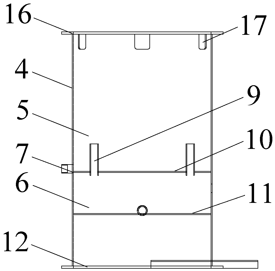
[0015] like Figure 1~Figure 4 As shown, the present invention includes an atomizer 1, and the atomizer 1 includes a connected lime slurry channel 2, an atomizing disc 3, and it also includes a cylinder 4 and a circulation pump 18 located outside the cylinder 4, and the cylinder 4 The interior is divided into a soaking area 5 and a storage area 6 by partitions, and the cylinder 4 at the bottom of each area is provided with a sewage outlet 7, and each sewage outlet 7 is connected to a sewage tap 8, and the atomizer 1 is installed in the cylinder 4, and place the atomizing disc 3 in the soaking area 5, the storage area 6 is connected to the circulation pump 18 and communicates with the lime slurry channel 2, and the water hole 9 with a height higher than the atomizing disc 3 is arranged on the partition plate, A cleaning solution is added to the storage area 6, and the cleaning solution is a citric acid solution with a concentration of 30% to 50%.

[0016] The dividing plate co...


PUM


Abstract

The invention provides a cleaning device for a high-speed rotary atomizer. The cleaning device can efficiently clean away lime slurry adhering to an atomizing disc, the maintenance time is shortened,dynamic balance of the atomizing disc can also be guaranteed, and the service life of the equipment is prolonged; the cleaning device comprises the atomizer, the atomizer comprises a lime slurry channel and the atomizing disc which are communicated with each other, the atomizer further comprises a cylinder and a circulating pump arranged outside the cylinder, the interior of the cylinder is divided into a soaking area and a storing area by a clapboard, a sewage draining opening is formed in the position, at the bottom of each area, of the cylinder, the atomizer is installed on the cylinder, the atomizing disc is arranged in the soaking area, the storing area is communicated with the lime slurry channel after being connected with the circulating pump, the clapboard is provided with a waterpassing hole which is higher than the atomizing disc, and cleaning liquid is added into the storing area.

Description

technical field [0001] The invention relates to the technical field of atomization equipment, in particular to a cleaning device for a high-speed rotary atomizer. Background technique [0002] When the semi-dry process is used to deacidify (SO2, HCl) the waste incineration power plant flue gas, the high-speed rotary atomizer is widely used in the atomization of lime slurry, and its efficient and stable atomization effect is that the flue gas can It is an important guarantee to meet the emission standards, but due to the limitations of the existing lime production quality and the operating environment of the atomizer, after a period of continuous use of the atomizer, a large amount of dried lime slurry will stick to the surface of the atomizer and the surface of the atomizer. In the nozzle hole, in severe cases, the buffer distribution area of ​​the atomizer body will be blocked. This phenomenon will not only destroy the dynamic balance of the atomization disc, make the vibra...

Claims


Application Information

Patent Timeline
IPC IPC(8): B05B15/55
Inventor 蒋洪元王飞飞
Owner WUXI XUELANG ENVIRONMENTAL TECH CO LTD
Learn More