
Multi-break high-voltage system-based current-limiting device

A technology of high-voltage systems and current limiting devices, which is applied in the direction of emergency protection circuit devices, circuit devices, emergency protection circuit devices, etc. for limiting overcurrent/overvoltage, and can solve users' large economic burdens, user end voltage reduction, huge Reactive power loss and other issues, to achieve the effect of simple structure, reduced impact, strong breaking capacity

Pending Publication Date: 2018-05-18
ANHUI YIGE RUIDE ELECTRIC EQUIP CO LTD
View PDF6 Cites 3 Cited by
  • Summary
  • Abstract
  • Description
  • Claims
  • Application Information

AI Technical Summary

Problems solved by technology

However, the series current-limiting reactor has many shortcomings. First, the huge reactive power loss in the series circuit of the current-limiting reactor also causes a great economic burden to the user; secondly, when selecting the reactance value of the current-limiting reactor , there is often a contradiction that the voltage at the user end is too low under the rated current after meeting the requirements for limiting the short-circuit current
In the long-distance transmission process of the transmission and distribution network of the power system, the transmission line will also generate inductive reactance, which is equivalent to forming an invisible and potential reactor in the load circuit of the user in series, which also causes the voltage at the user end to decrease, and at the same time There is also a large reactive power loss

Method used


Image

  • Multi-break high-voltage system-based current-limiting device

Examples


Embodiment Construction

[0009] The present invention will be further described below in conjunction with accompanying drawing:

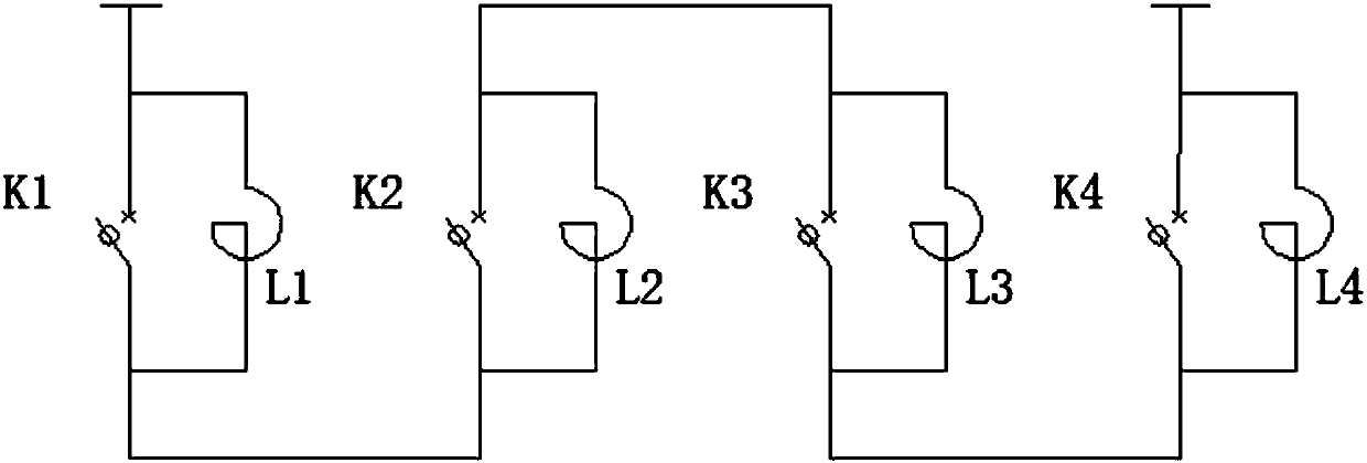
[0010] like figure 1 As shown, the current limiting device based on the multi-fracture high-voltage system in this embodiment includes a high-speed eddy current switch K1, a high-speed eddy current switch K2, a high-speed eddy current switch K3, and a high-speed eddy current switch K4 connected in series. The incoming line terminal of the electric cabinet is connected, the outgoing line end of the high-speed eddy current switch K4 is connected with the outgoing line end of the power distribution cabinet, the two ends of the high-speed eddy current switch K1 are connected in parallel with the limited current reactor L1, and the two ends of the high-speed eddy current switch K2 are connected in parallel with the limited current reactor L2, a current-limiting reactor L3 is connected in parallel at both ends of the high-speed eddy current switch K3, and a current-limiting react...


PUM


Abstract

The invention relates to a multi-break high-voltage system-based current-limiting device. The multi-break high-voltage system-based current-limiting device comprises high-speed eddy switches K1, K2, K3 and K4, wherein an incoming line end of the high-speed eddy switch K1 is connected with an incoming line end of a power distribution cabinet, an outgoing line end of the high-speed eddy switch K4 isconnected with an outgoing line end of the power distribution cabinet, a current-limiting reactor L1 is connected in parallel with two ends of the high-speed eddy switch K1, a current-limiting reactor L2 is connected in parallel with two ends of the high-speed eddy switch K2, a current-limiting reactor L3 is connected in parallel with two ends of the high-speed eddy switch K3, and a current-limiting reactor L4 is connected in parallel with two ends of the high-speed eddy switch K4. The multi-break high-voltage system-based current-limiting device has the advantages of high breaking capability, simple structure, rapid action and the like, the short-circuit strength can be effectively limited by the current-limiting reactors, the impact of a short-circuit current on electrical equipment isgreatly reduced, and zero loss of the current-limiting reactors during normal running can be achieved.

Description

technical field [0001] The invention relates to the technical field of high-voltage current-limiting reactors, in particular to a multi-break high-voltage system current-limiting device. Background technique [0002] With the development of economy, with the sharp increase of electric load, the increase of power grid capacity, the continuous improvement of high-voltage transmission level, and the impact of increasing short-circuit current on electrical equipment of power system is getting bigger and bigger; at the same time, the existing The breaking capacity of current circuit breakers has been difficult to meet the breaking of huge short-circuit current, and under such a large voltage level, the insulation of existing circuit breakers is difficult to meet the requirements. Therefore, in order to solve this major problem, the current-limiting reactor is widely used in the transmission and distribution system of the power system by being connected in series. The current-lim...

Claims


Application Information

Patent Timeline
IPC IPC(8): H02H9/02
CPCH02H9/02
Inventor 王炎张国勇茅东虞江华宋安超于浩
Owner ANHUI YIGE RUIDE ELECTRIC EQUIP CO LTD
Learn More