
Fabrication method of I-shaped inductor capable of surface-mounting

A technology of I-shaped inductors and manufacturing methods, which is applied in the field of inductors, can solve the problems of failure to pass environmental protection certification, huge price differences, and high product costs, and achieve the effect of meeting the requirements of automated production, increasing costs, and realizing fully automated production

Inactive Publication Date: 2018-05-18
王强
View PDF6 Cites 4 Cited by
  • Summary
  • Abstract
  • Description
  • Claims
  • Application Information

AI Technical Summary

Problems solved by technology

However, for the I-shaped magnetic core of this patent, the pins, winding solder and then directly inserted on the through patch base, the method of folding the pins parallel to the base, and then printing and taping, because this type of base is usually made of plastic material, different The price of materials varies greatly. Although the price of the patch base made of cheap materials is cheap, the products cannot pass the environmental certifications such as REACH and halogen-free. However, for materials that meet environmental certification, the minimum price of a single base is more than 0.02-0.03 yuan , which is reflected in the cost of the entire product is expensive and fatal; secondly, this method makes the solder joints of the entire inductor small, and the contact surface of the inductor pad is generally only as thick as the pin diameter, and the inductor itself is made of ferrite material and copper wire The average weight of the product is more than 3-5 grams. The copper foil of the PCB patch board is generally very thin, and it is covered on the surface of the PCB to form a circuit diagram; in the optoelectronic integration, the inductor and the lamp bead are on the same plane, installed on the The lamp holder is vertically downward, and due to gravity, there will be a lot of pulling force on the solder joints, resulting in serious quality problems, so this solution is not the best

Method used

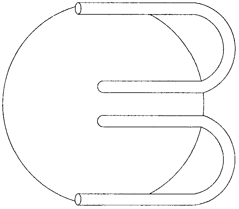
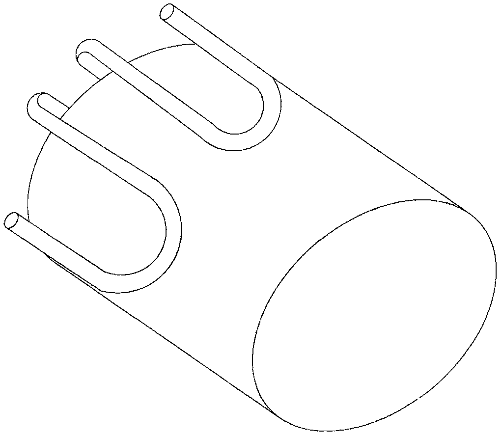

Image

  • Fabrication method of I-shaped inductor capable of surface-mounting
  • Fabrication method of I-shaped inductor capable of surface-mounting
  • Fabrication method of I-shaped inductor capable of surface-mounting

Examples


Embodiment 1

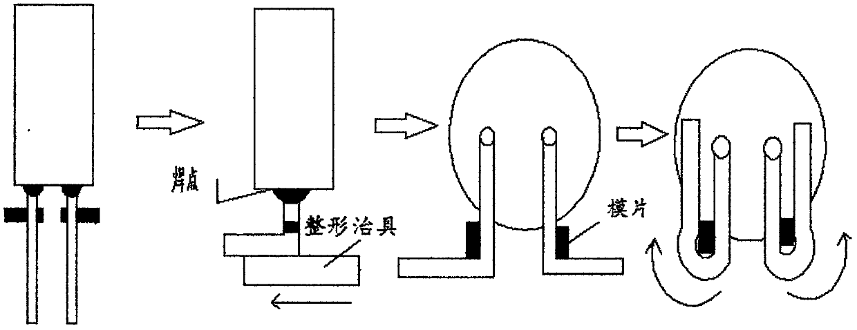
[0029] The manufacture method of the patch type vertical I-shaped inductor of the present invention, such as image 3 shown, including the following specific steps:

[0030] Step S101. Wind the nickel-zinc or magnesium-zinc ferrite vertical I-shaped inductor magnetic core with sticky pins, then soak the pins in a tin furnace at 420-450°C for 3-5 seconds, and wrap the enamelled copper wire Burn off the paint, and then stick the inductance pins with flux and dip tin in the tin furnace for 3-5 seconds, where the flux is zinc chloride solution or ethanol rosin solution or propanol rosin solution;

[0031] Step S102, encapsulating the soldered I-shaped inductor with a heat-shrinkable sleeve or with a packaging coating, wherein the heat-shrinkable sleeve is a PVC heat-shrinkable tube or a PE heat-shrinkable tube; the packaging coating is bisphenol A Type epoxy resin, novolac modified epoxy resin or aliphatic epoxy resin;

[0032] Step S103, cutting the encapsulated I-shaped induct...

Embodiment 2

[0036] The manufacturing method of the patch type horizontal I-shaped inductor of the present invention comprises the following specific steps:

[0037] Step S101, first use the DR cutting machine to cut the wire groove of the rod-shaped iron powder core with pinholes, and then coat the cut I-shaped iron powder core with epoxy resin coating for insulation treatment ;Insulate the vertical I-shaped iron powder core core with pins and wires, then soak the pins in a tin furnace at 420-450°C for 2-3 seconds to burn off the paint skin of the enamelled copper wire, Then stick the inductance pins with flux and dip tin in the tin furnace for 2-3 seconds, where the flux is zinc chloride solution or ethanol rosin solution or propanol rosin solution;

[0038] Step S102, encapsulating the soldered I-shaped inductor with a heat-shrinkable sleeve or with a packaging coating, wherein the heat-shrinkable sleeve is a PVC heat-shrinkable tube or a PE heat-shrinkable tube; the packaging coating i...


PUM


Abstract

The invention discloses a fabrication method of an I-shaped inductor capable of surface-mounting. The method comprises the following steps of S101, winding a magnetic core pin of the I-shaped inductor, burning a paint skin of a pin enameled copper wire, and immersing tin for 3-5 seconds; S102, encapsulating the I-shaped inductor welded with the tin; S103, performing pin shearing on the I-shaped inductor of which encapsulation is completed; S104, folding and straightening a pin of the I-shaped inductor of which the pin length is cut; and S105, pasting a die sheet with a thickness being 0.3-1 millimeter of a pin cushion onto two sides of the pin of the I-shaped inductor of which the pin is straightened, folding the straightened inductor pin towards an opposite direction by a clamp or by manual, and completing the surface-mounting formation process of the whole inductor. The inductor produced by the method is low in cost and simple and practical in structure, the contact surface of a bonding pad after a patch is processed is large, full-automatic production can be achieved, and the production efficiency and the additive value of a finished product are improved.

Description

technical field [0001] The invention belongs to the technical field of inductors, in particular to a method for manufacturing a chip-type I-shaped inductor. Background technique [0002] With the continuous decline in the price of LED lighting products and the popularization of civilian products, the price of LED bulbs with 7 watts as an example has dropped from 10-13 yuan three years ago to 2-4 yuan. On the one hand, it depends on the price reduction of a large number of parts. On the other hand, relying on the use of plastic-coated aluminum heat dissipation materials effectively solves the insulation problem. The non-isolated constant current switching power supply is widely used in the bulb lamp, because the non-isolated constant current switching power supply has a simple structure, few peripheral components, and low cost. However, in the traditional non-isolated constant current switching power supply, most of the components are plug-ins, and domestic labor costs have ...

Claims


Application Information

Patent Timeline
Patent Type & Authority Applications(China)
IPC IPC(8): H01F41/00H01F41/10
CPCH01F41/005H01F41/00H01F41/10
Inventor 王强
Owner 王强
Learn More