
Mute high-speed pipe-interior pump and complete-set pressurizing device

A pump-in-pipe, high-speed technology, applied in pump devices, valve devices, components of pumping devices for elastic fluids, etc. and vibration increase to achieve the effect of reducing vibration, ensuring high speed and reducing vibration

Pending Publication Date: 2018-05-18
宙斯流体系统(上海)有限公司
View PDF13 Cites 3 Cited by
  • Summary
  • Abstract
  • Description
  • Claims
  • Application Information

AI Technical Summary

Problems solved by technology

[0002] In the traditional tube pump, the motor and the pump body are installed on both ends of the sleeve through the shaft sleeve. This installation method requires high precision in production and installation, because the length of the tube pump is long. Or when assembling, the concentricity of the motor, the pump body and the rotating shaft will have a slight deviation, which will make it difficult to install the pump in the pipe. Even if the installation is barely completed, the pump in the pipe will generate large vibration and noise during subsequent use. As the running time of the pump in pipe increases, the deviation will gradually increase, and the noise and vibration will further increase, seriously affecting the operation, maintenance and service life of the pump in pipe

Method used


Image

  • Mute high-speed pipe-interior pump and complete-set pressurizing device
  • Mute high-speed pipe-interior pump and complete-set pressurizing device
  • Mute high-speed pipe-interior pump and complete-set pressurizing device

Examples


Embodiment 1

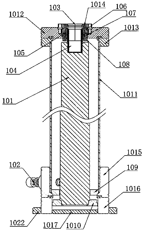
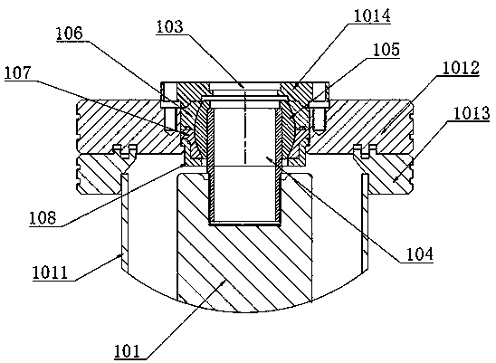
[0057] Embodiment 1: as figure 1 and figure 2 As shown, a silent high-speed pipe pump includes a pump casing and a submersible pump 101, the side of the pump casing is provided with a water inlet 102, and the top of the pump casing is provided with a water outlet 103, and the submersible pump 101 is installed on In the pump casing, the top of the submersible pump 101 is provided with a positioning shaft 104, the positioning shaft 105 is provided with a positioning shaft through hole, and the positioning shaft through hole is connected with the submersible pump 101, and the upper end of the pump casing is provided with The first positioning seat, the lower end of the pump casing is provided with a second positioning seat, the first positioning seat includes a ball bowl and a ball head 105, the ball bowl is connected with the pump casing around, and the ball head 105 is installed on the ball In the bowl, the ball head 105 is provided with a vertical through hole, the positioni...

Embodiment 2

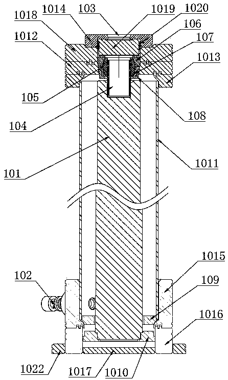
[0063] Embodiment 2: As a kind of improved scheme of embodiment 1, such as Figure 3 to Figure 10As shown, a third top flange 1018 is also provided between the top cover plate 1014 and the first top flange 1012, and a third ring is provided between the first top flange 1012 and the third top flange 1018. shaped tongue and groove structure, a check valve 1019 is installed in the flange hole of the third top flange 1018, and a side wall flange 2014 is provided on the valve seat side wall 2012 of the check valve 1019, and the side wall The flexible seal 1020 and the first sealing thrust seat 1021 are sequentially sleeved under the flange 2014. The first sealing thrust seat 1021 includes a thrust side plate and a thrust bottom plate. The upper end of the thrust side plate is connected to the flexible seal 1020. connection, the upper surface of the thrust bottom plate is connected with the check valve 1019, the lower surface of the thrust bottom plate is connected with the upper se...

Embodiment 3

[0068] Embodiment 3: as Figure 11 and Figure 12 As shown, a complete booster device includes a mounting plate 1028 and four silent high-speed pipe pumps, and the four silent high-speed pipe pumps are all installed on the mounting plate 1028, and the four silent high-speed pipe pumps are respectively The first silent high-speed pipe pump 1023, the second silent high-speed pipe pump 1025, the third silent high-speed pipe pump 1024 and the fourth silent high-speed pipe pump 1026, the first silent high-speed pipe pump 1023 and the second The pumps in the quiet high-speed pipe 1025 are connected in series to form a first pump group, and the pumps 1024 in the third quiet high-speed pipe and the pump 1026 in the fourth quiet high-speed pipe are connected in series to form a second pump group. The first pump group and the second pump group in parallel.

[0069] In this embodiment, the first silent high-speed pipe pump 1023 and the third silent high-speed pipe pump 1024 select the ...


PUM


Abstract

The invention discloses a mute high-speed pipe-interior pump and a complete-set pressurizing device and belongs to the technical field of environment protection. The pipe-interior pump comprises a pump shell and an immersible pump, a water inlet is formed in the side face of the pump shell, and a water outlet is formed in the top of the pump shell. The immersible pump is mounted in the pump shell,a positioning shaft is arranged at the top of the immersible pump, and a positioning shaft through hole is formed in the positioning shaft and communicates with the immersible pump. A first positioning seat is arranged at the upper end of the pump shell, a second positioning seat is arranged at the lower end of the pump shell, and the first positioning seat comprises a ball bowel and a linkage ball. The periphery of the ball bowel is connected with the pump shell, the linkage ball is mounted in the ball bowel, and a vertical through hole is formed in the linkage ball. The positioning shaft isarranged in the vertical through hole of the linkage ball in a penetrating mode, the positioning shaft through hole communicates with the water outlet, and the lower end of the immersible pump is mounted in the second positioning seat. The complete-set pressurizing device comprises the four mute high-speed pipe-interior pumps which are combined in series-connection and parallel-connection modes.According to the pipe-interior pumps, operation is stable, noise is low, and the service life is long; and according to the complete-set pressurizing device, the pressure is high, the flow is large, and the application range is wide.

Description

technical field [0001] The invention belongs to the technical field of environmental protection, in particular to a silent high-speed in-pipe pump and a complete booster device. Background technique [0002] In the traditional tube pump, the motor and the pump body are installed on both ends of the sleeve through the shaft sleeve. This installation method requires high precision in production and installation, because the length of the tube pump is long. Or when assembling, the concentricity of the motor, the pump body and the rotating shaft will have a slight deviation, which will make it difficult to install the pump in the pipe. Even if the installation is barely completed, the pump in the pipe will generate large vibration and noise during subsequent use. As the running time of the pump in pipe increases, the deviation will gradually increase, and the noise and vibration will further increase, which will seriously affect the operation, maintenance and service life of the...

Claims


Application Information

Patent Timeline
Patent Type & Authority Applications(China)
IPC IPC(8): F04D13/08F04D29/62F04D29/66F04D29/42F04D13/14F04D15/00F16K15/06F16K1/38
CPCF04D13/086F04D13/14F04D15/0005F04D15/0072F04D29/426F04D29/628F04D29/669F16K1/38F16K15/063
Inventor 顾炎彬
Owner 宙斯流体系统(上海)有限公司
Learn More