Pump body components and compressors

A technology of components and pump bodies, applied in pump elements, liquid fuel engines, components of pumping devices for elastic fluids, etc., can solve problems such as insufficient air supply and poor energy efficiency of compressors

Active Publication Date: 2019-08-06
ZHUHAI LANDA COMPRESSOR +1
View PDF6 Cites 0 Cited by
  • Summary
  • Abstract
  • Description
  • Claims
  • Application Information

AI Technical Summary

Problems solved by technology

[0004] Due to the above-mentioned structural limitations, the existing compressor air supply structure is insufficient, resulting in poor energy efficiency of the compressor

Method used


Image

  • Pump body components and compressors
  • Pump body components and compressors
  • Pump body components and compressors

Examples


Embodiment Construction

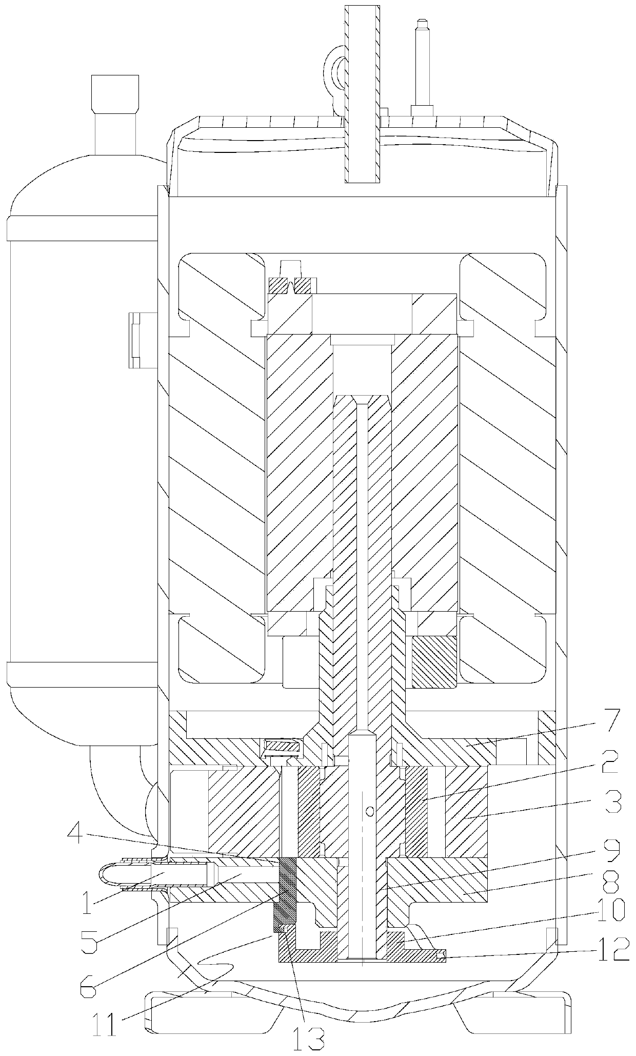
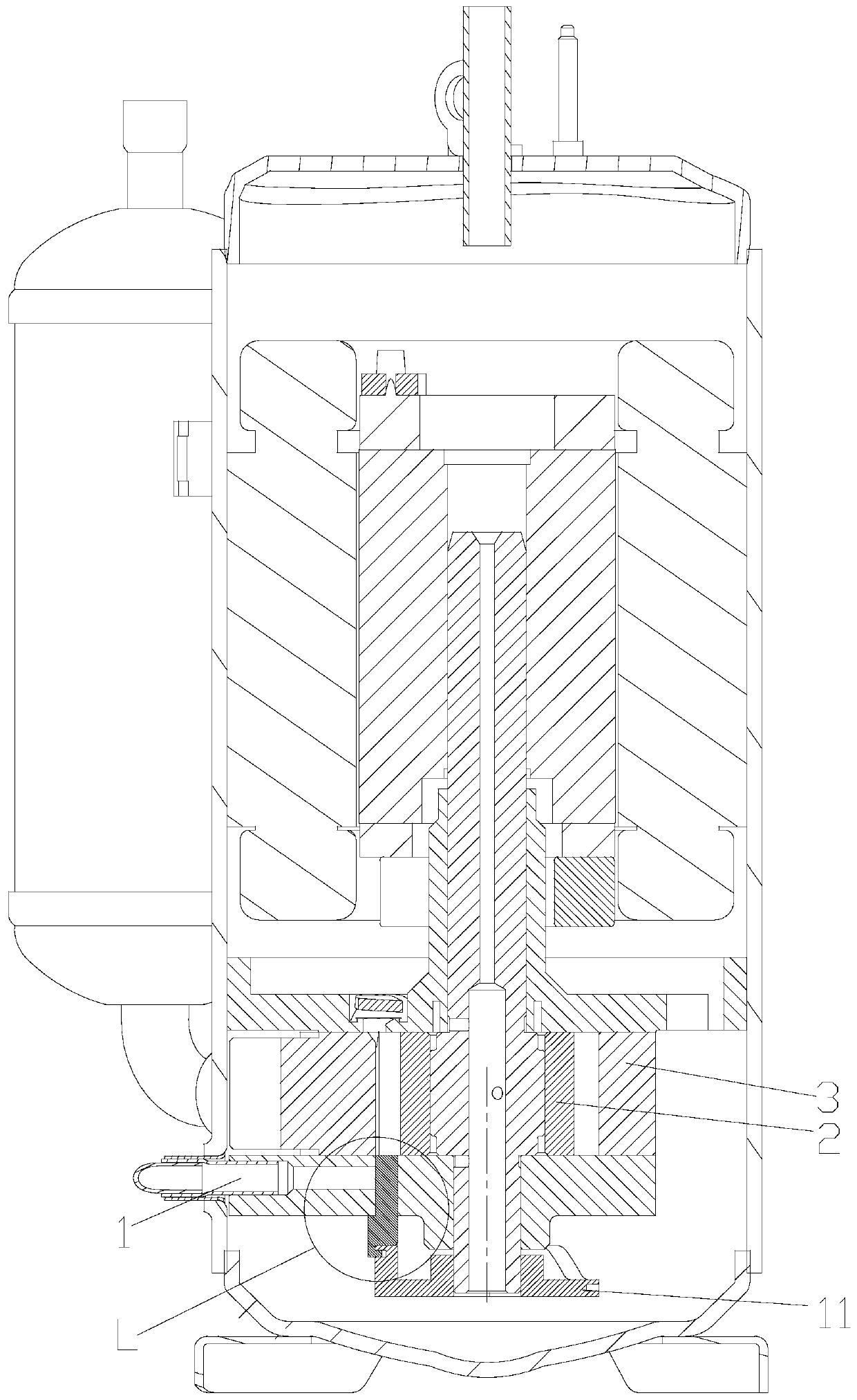
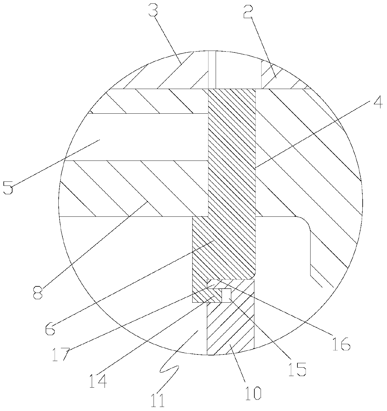
[0038] see in conjunction Figures 1 to 10 As shown, according to the embodiment of the present invention, the pump body assembly includes a suction port, an air supply port 1, a roller 2 and a cylinder 3, the cylinder 3 has a working chamber, and a valve hole 4 is also arranged in the pump body assembly, and the valve hole 4 One end communicates with the working chamber. There is an air supply channel 5 between the air supply port 1 and the valve hole 4. A valve core 6 is slid inside the valve hole 4. The valve core 6 is used when the roller 2 separates the air supply port 1 from the suction port. The gas supply port 1 communicates with the compression cavity of the working cavity, and / or closes the gas supply channel 5 when the pressure of the compression cavity of the working cavity is greater than the gas supply pressure.

[0039] During the air supply process of the compressor, the air supply channel 5 can be opened or closed by the movement of the valve core 6 in the val...


PUM


Abstract

A pump assembly and a compressor. The pump assembly comprises an air suction port, an air supplementing port (1), a roller (2), and an air cylinder (3). The air cylinder (3) has an operating cavity. A valve hole (4) is further provided in the pump assembly. One end of the valve hole (4) communicates with the operating cavity. An air supplementing channel (5) is provided between the air supplementing port (1) and the valve hole (4). A spool (6) is slidably disposed in the valve hole (4). The air supplementing port (1) communicates with a compression cavity of the operating cavity by means of the spool (6) when the roller (2) separates the air supplementing port (1) from the air suction port, and / or the spool (6) closes the air supplementing channel (5) when a pressure of the compression cavity of the operating cavity is higher than an air supplementing pressure. The pump assembly avoids reflux of air supplemented to a compressor, thereby ensuring that sufficient air is supplemented to the compressor, and improving energy efficiency of the compressor.

Description

technical field [0001] The invention belongs to the technical field of air compression, and in particular relates to a pump body assembly and a compressor. Background technique [0002] At present, there are two types of air supply technologies for single-cylinder compressors. One is to open the air supply port on the cylinder near the compressor exhaust port, and the other is to open the air supply port on the upper or lower flange. [0003] The main disadvantage of these two structures is that it is impossible to prevent the injected refrigerant from flowing back to the suction pipe, or the area of ​​the injection port is limited, which leads to unsatisfactory performance of the compressor. If the air supply port is set on the cylinder, when the roller turns over the air supply port, the air supply port communicates with the suction hole, so that the supply air flows back to the suction hole, reducing the energy efficiency of the compressor. When the air supply port is se...

Claims


Application Information

Patent Timeline
Patent Type & Authority Patents(China)
IPC IPC(8): F04C29/12F04C28/00
CPCF04C28/00F04C29/124
Inventor 刘达炜张洪钰
Owner ZHUHAI LANDA COMPRESSOR
Why Eureka
Try Eureka