Automatic rotation door device

An automatic turning and door device technology, applied in door/window fittings, power control mechanisms, switches with brakes, etc., can solve the problems of potential safety hazards, the revolving door cannot be opened automatically, and people's troubles, so as to improve safety sexual effect

Active Publication Date: 2018-05-18
CHONGQING WEIRUI TECH CO LTD
View PDF7 Cites 1 Cited by
  • Summary
  • Abstract
  • Description
  • Claims
  • Application Information

AI Technical Summary

Problems solved by technology

[0005] Although the above-mentioned patent solution solves the problem of automatic rebound after the automatic door is opened, it does not consume electric energy and achieves labor-saving and energy-saving effects, but there are still the following problems: 1. When people enter and exit the door, the revolving door cannot automatically To open, you can only push the door manually, causing troubles to people who carry heavy objects or have inconvenient hands and feet; 2. When people go in and out of the door, they will bump into the door if they are not careful, which will bring safety hazards to people

Method used


Image

  • Automatic rotation door device
  • Automatic rotation door device
  • Automatic rotation door device

Examples


Embodiment Construction

[0028] Further detailed explanation through specific implementation mode below:

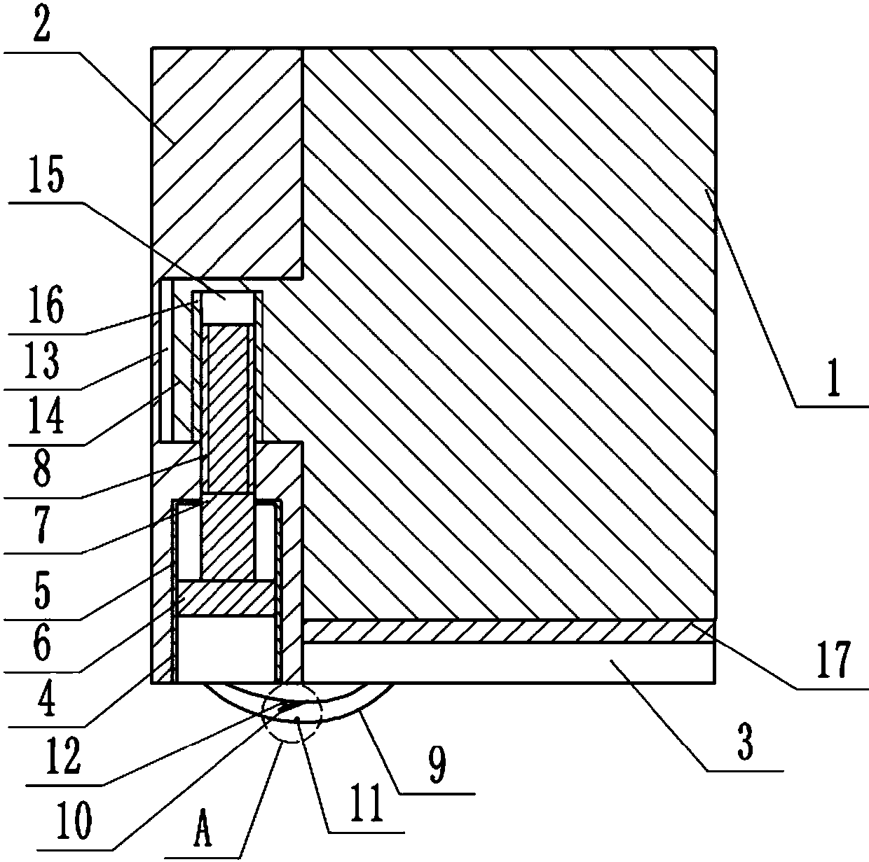
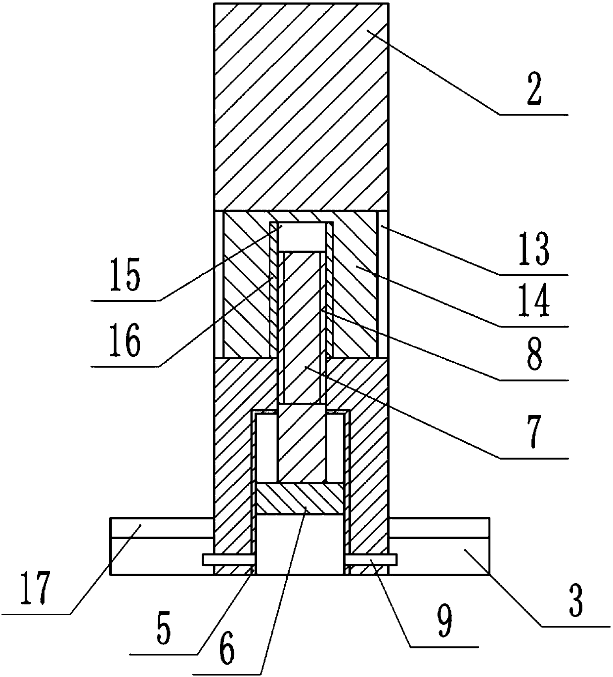
[0029] The reference signs in the drawings of the specification include: door leaf 1, door shaft 2, liquid bag 3, hydraulic cylinder 4, cylinder body 5, piston 6, piston rod 7, external thread 8, pipe 9, baffle 10, blocking part 11 , Elastic part 12, groove 13, rotating block 14, cylindrical groove 15, internal thread 16, pedal 17.

[0030] Such as figure 1 with figure 2 As shown, the automatic revolving door device of the present invention includes a door leaf 1 and a door shaft 2, and the front and rear of the door leaf 1 are provided with a liquid bag 3 placed on the ground. The liquid bag 3 is a whole, and a pedal 17 is laid on the liquid bag 3. A pit can be dug on the ground before and after the door, the liquid bag 3 and the pedal 17 are placed in the pit, and then the surroundings of the pedal 17 are fixed on the ground so that the pedal 17 is flush with the ground, so that people can e...


PUM


Abstract

The invention discloses an automatic rotation door device, and relates to the field of building moving type closing devices. The automatic rotation door device includes a door shaft and a door sash. The front and back of the door sash are provided with liquid bladders. The door shaft is internally provided with a hydraulic cylinder. A piston rod of the hydraulic cylinder is provided with outer threads. Pipelines are arranged between the liquid bladders on the front and back of the door and the hydraulic cylinders. The inner wall of each pipeline is connected with a baffle plate tilting towardsone side of the hydraulic cylinder. The other side of the connecting position of each baffle plate and the corresponding pipeline is provided with a blocking part used for limiting tilting of the baffle plate towards the liquid bladder direction. A flexible assembly is arranged between each baffle plate and each pipeline inner wall. A groove is formed in the door shaft. A rotation block insertedinto the groove is fixedly connected to the door sash. The rotation block is in rotation cooperation with the groove. The rotation block is internally provided with a cylindrical groove. The surface of the cylindrical groove is provided with inner threads matched with the outer threads of the piston rod. According to the automatic rotation door device, the problem that an existing rotation door which does not consume electricity cannot be opened and closed automatically is solved; the automatic rotation door device is mainly used in a family or a public area; through action of own gravity of people, automatic opening and closing of the door sash can be achieved.

Description

technical field [0001] The invention relates to the field of building movable closing devices, in particular to an automatic revolving door device. Background technique [0002] With the development of the automatic door industry, automatic doors are more and more popular among people. Nowadays, many automatic doors are applied to many public places. The existing automatic sliding door system generally recognizes the action of people approaching the door (or some kind of entry authorization) as a door opening signal through the control unit, then opens the door through the drive system, and automatically closes the door after the person leaves. The opening and closing process realizes the control system. [0003] Although the existing automatic doors are neat and elegant, easy to use, and easy to control, they have defects such as high price, many wearing parts, large anti-pinch force, and large power consumption. The rotary curtain type electric door needs to manually pul...

Claims


Application Information

Patent Timeline
Patent Type & Authority Applications(China)
IPC IPC(8): E05F15/75E05F15/53E05F5/06
CPCE05F5/06E05F15/53E05F15/75
Inventor 袁亮
Owner CHONGQING WEIRUI TECH CO LTD
Why Eureka
Try Eureka