
Semi-annular-wing aircraft

An aircraft and ring-wing technology, applied in the field of aircraft, can solve the problems of lack of large-scale popularization, insufficient surplus power, and high maintenance costs, and achieve the effects of high reliability and safety, stable attitude, and large carrying capacity.

Pending Publication Date: 2018-05-18
宿迁永泰邦辰知识产权运营管理有限公司
View PDF0 Cites 3 Cited by
  • Summary
  • Abstract
  • Description
  • Claims
  • Application Information

AI Technical Summary

Problems solved by technology

[0006] In the history of aviation, there has also been a semi-ring wing (Half ring wing) aircraft, which has a semi-ring appearance, which is equivalent to half of the ring wing, and is placed on both sides of the aircraft. Good lift, short take-off and landing advantages are very obvious, but due to various reasons, this semi-ring wing aircraft has not been widely used
[0007] In recent years, with the rise of the U.S. V22 Osprey tilt-rotor aircraft, countries are strengthening the research on tilt-rotor aircraft. V22 not only has the ability of ordinary helicopters to take off and land and hover in the air, but also has the ability of high-speed cruise flight of fixed-wing aircraft. Capability, the advantage is quite obvious, but the disadvantages of the V22 are also quite obvious, the structure is complex, the maintenance cost is high, the wing load is high, and the surplus power is insufficient during vertical take-off and landing, resulting in frequent failures

Method used


Image

  • Semi-annular-wing aircraft
  • Semi-annular-wing aircraft
  • Semi-annular-wing aircraft

Examples


Embodiment 1

[0041] Example 1: Takeoff

[0042] 1. Slide mode

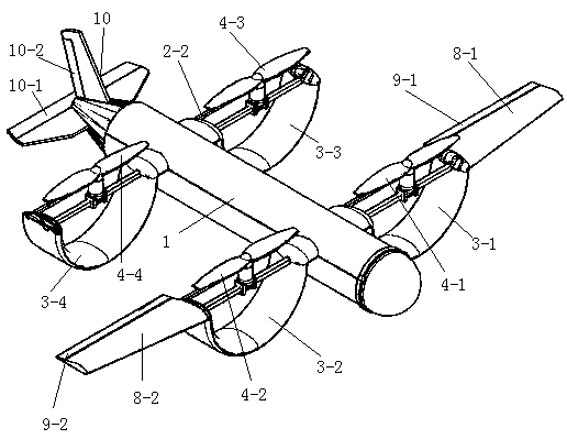
[0043] Use the landing gear to take off on the runway, and the steering gear 18 controls the flaps 9 to turn down to increase the lift. At this time, the angle of the rotating device 2 is at 0°, and the propeller 4 generates backward thrust, and the steering gear 18 controls the elevator. 10-1 turns downward, the aircraft generates a head-up moment, and the aircraft leaves the ground. As the flight speed of the aircraft gradually increases, the steering gear 18 controls the elevator 10-1 to turn upward, and the aircraft generates a head-down moment to balance the attitude of the aircraft. Steering gear 18 controls flap 9 to retract, thereby enters level flight state.

[0044] 2. Short takeoff

[0045] The angle of the rotating device 2 is adjusted by the controller, usually between 0° and 90°. The steering gear 18 controls the flaps 9 to turn down to increase the lift. At this time, the thrust generated by the propeller 4 is...

Embodiment 2

[0048] Example 2: Attitude in the air

[0049] 1. Hover

[0050] The angle of the rotating device 2 is adjusted by the controller. At this time, the rotating device 2 is in the 90° position, and the thrust produced by the propeller 4 is vertically downward. When the control thrust is the same as the weight of the aircraft, the aircraft is in a hovering state.

[0051] 2. Somersault in the air

[0052] In the hover attitude, by increasing the thrust of the left propeller (4-1, 4-3) of the aircraft, and reducing the thrust of the right propeller (4-2, 4-4), at the same time, the steering gear 18 controls the rudder 10-2 Flip to the right, because of the power difference on both sides of the aircraft, a rightward yaw moment will be generated on the aircraft, otherwise, a leftward yaw moment will be generated, and it can also turn back and forth.

[0053] 3. Normal flight

[0054] Same as the roll take-off, the rotation device 2 angle of the aircraft is at the 0° position, and ...

Embodiment 3

[0060] Example 3: Landing

[0061] 1. Vertical landing

[0062] By adjusting the angle of the rotating device 2, the rotating device 2 is at a position of 90° at this time, and the thrust produced by the propeller 4 is vertically downward, and by reducing the thrust, the thrust is gradually smaller than the weight of the aircraft, so that the vertical landing of the aircraft is realized.

[0063] 2. Short-distance landing

[0064] Adjust the angle of the rotating device 2 through the controller, usually between 0° and 90°. At this time, the thrust generated by the propeller 4 is obliquely rearward, and the thrust can be decomposed into forces in two directions, forward and upward, and then gradually lower the propeller. 4 thrust, while the steering gear 18 controls the elevator 10-1 to turn upwards, and the aircraft produces a nose-down moment to realize the short-distance landing of the aircraft.

[0065] 3. Rolling and landing

[0066] At this time, the angle of the rotat...


PUM


Abstract

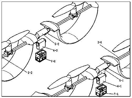
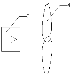
The invention discloses a semi-annular-wing aircraft. The semi-annular-wing aircraft comprises a steering engine, a propeller, a fuselage, an empennage and semi-annular wings connected with the fuselage, wherein the propeller is used for controlling a flight attitude through a controller; four sets of the semi-annular wings are arranged, and are symmetrically mounted at two sides of the fuselage;ailerons are arranged at edges of the semi-annular wings of a front row respectively; the propeller is correspondingly mounted above the semi-annular wings through a rotating device; the controller isused for controlling the angle of the propeller through the rotating device; the empennage comprises an elevating rudder and a yaw rudder; the elevating rudder is used for controlling a pitch attitude of the aircraft and the yaw rudder is used for controlling a yaw attitude of the aircraft. The aircraft provided by the invention is simple in structure; elevating force generated by the semi-annular wings is much greater than that of wings of a helicopter; the aircraft has the characteristics of great loading weight, rapid flight speed, far flying range, small noises, low energy consumption andthe like.

Description

technical field [0001] The invention relates to an aircraft, in particular to a semi-circular wing aircraft. Background technique [0002] An aircraft is a device that can fly in the atmosphere or outside the atmosphere (space). Aircraft mainly include rotors and fixed-wings, such as helicopters, fixed-wing aircraft, and multi-rotor aircraft. [0003] Because helicopters can take off and land vertically, they have very low requirements for takeoff and landing conditions, especially runways, so they are widely used, such as sightseeing, fire rescue, sea first aid, anti-smuggling and anti-drug, fire fighting, commercial transportation, medical assistance, communication and spraying Pesticides and insecticides are used in various sectors of the national economy such as eliminating pests and detecting resources. However, the disadvantages of helicopters are also obvious, such as small load capacity, low practical ceiling, and especially low speed, which also limits its range of...

Claims


Application Information

Patent Timeline
IPC IPC(8): B64C27/08B64C27/32B64D27/26B64C1/30
CPCB64C1/30B64C27/08B64C27/32B64D27/40
Inventor 罗海洋
Owner 宿迁永泰邦辰知识产权运营管理有限公司
Learn More