
Multi-functional iron removal device for chemical industry material

A multi-functional, chemical technology, applied in the direction of drying granular materials, dust removal, drying gas arrangement, etc., can solve the problems of production equipment damage, poor iron removal effect, product quality problems, etc., and achieve the effect of preventing materials from entering and removing iron Good and practical effect

Inactive Publication Date: 2018-05-18
长沙德科投资管理咨询有限公司
View PDF3 Cites 1 Cited by
  • Summary
  • Abstract
  • Description
  • Claims
  • Application Information

AI Technical Summary

Problems solved by technology

[0002] At present, in the chemical industry, materials are often used as raw materials to produce solid products. These slurries may contain iron filings and other particles, and may also be mixed with iron filings during processing and storage; the existence of iron filings will cause quality problems in finished products. And sometimes it will cause damage to the production equipment, so it is necessary to use iron removal equipment to remove iron filings to ensure product quality and facilitate storage; the existing iron removal device has a poor iron removal effect and has no obvious effect on material treatment. , it is inconvenient to cut materials; at the same time, the function is single, and it does not have the function of dust removal and drying treatment of materials, which is not convenient for long-term storage of materials in the later stage; therefore, it needs to be improved

Method used


Image

  • Multi-functional iron removal device for chemical industry material
  • Multi-functional iron removal device for chemical industry material
  • Multi-functional iron removal device for chemical industry material

Examples


Embodiment Construction

[0016] The technical solution of this patent will be described in further detail below in conjunction with specific embodiments.

[0017] Embodiments of the present patent are described in detail below, examples of which are shown in the drawings, wherein the same or similar reference numerals designate the same or similar elements or elements having the same or similar functions throughout. The embodiments described below by referring to the figures are exemplary and are only used for explaining the patent, and should not be construed as limiting the patent.

[0018] In the description of this patent, it is to be understood that the terms "center", "upper", "lower", "front", "rear", "left", "right", "vertical", "horizontal", The orientation or positional relationship indicated by "top", "bottom", "inner", "outer", etc. is based on the orientation or positional relationship shown in the drawings, and is only for the convenience of describing this patent and simplifying the des...


PUM


Abstract

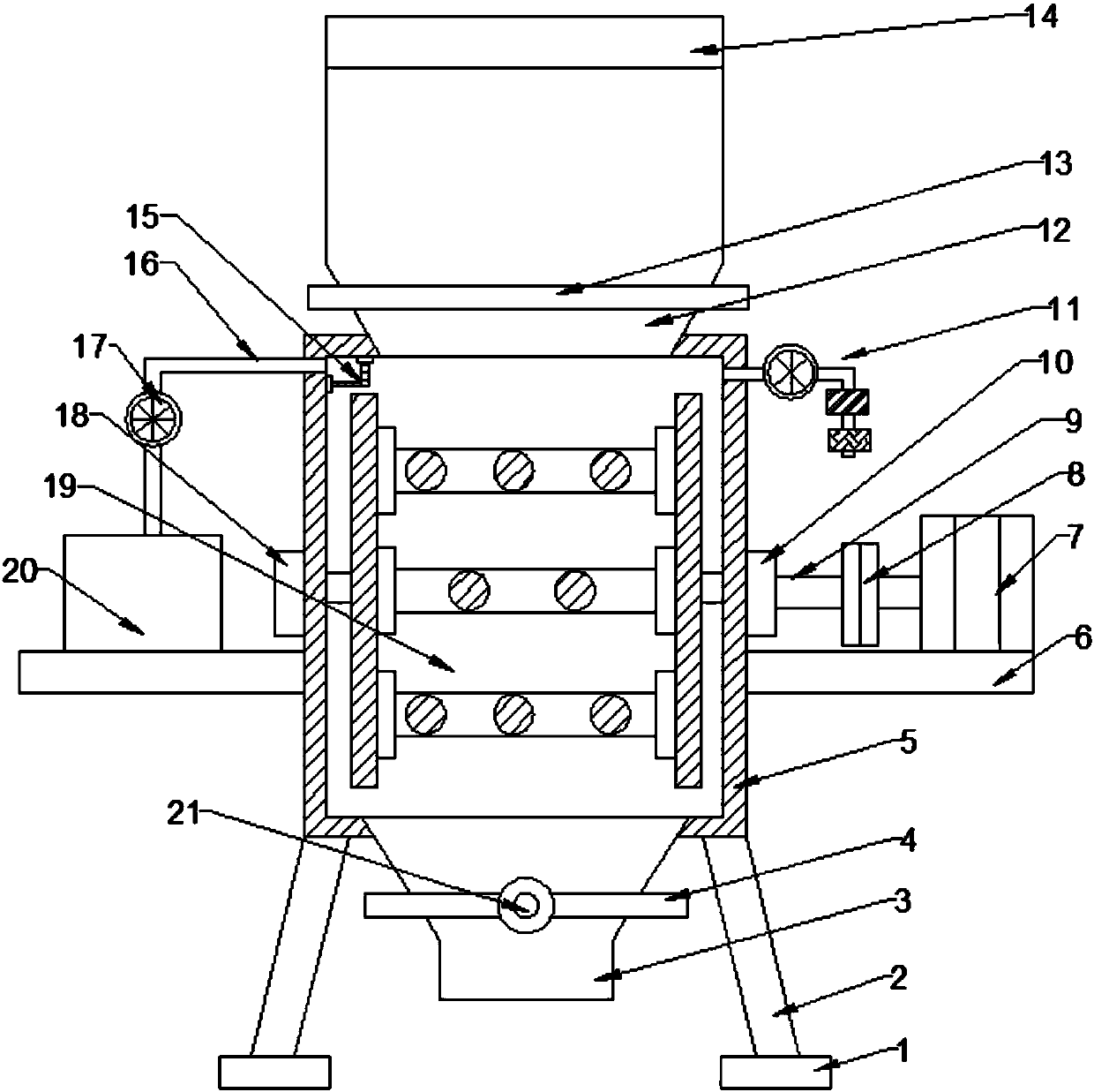
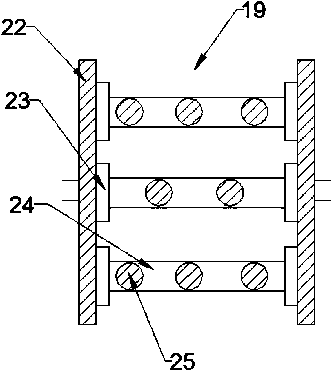
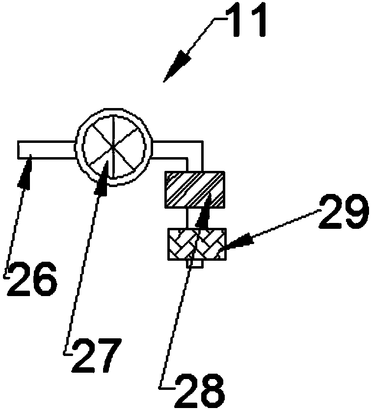
The invention provides a multifunctional iron removal device for chemical industry material, and belongs to the field of chemical industry. The multifunctional iron removal device for the chemical industry material comprises an iron removal device and a dust removal drying device. The control valve is arranged on a material hopper. The right end of the upper portion of a supporting plate is fixedly provided with a driving motor. The left end of the driving motor is connected with a right bearing through a coupling. The left end of the right bearing is provided with a rotating shaft. The iron removal device is arranged on the left side of the rotating shaft. The drying device is arranged on the upper end of the right side of a processing box. The upper end of a dust collecting box is connected with a suction fan by a dust suction pipe. Magnetic rods are arranged on connecting rods through fixing blocks, the magnetic rods on the connecting rods of each group are arranged in a staggered mode, so that the function of removing the iron from the material conveniently is achieved; the right end of a blower is connected with a heater by an air inlet pipe, the right end of the heater is provided with a filter, so that the function of removing fresh and hot air into the processing box to the dehumidification and drying of the material is achieved; and the multifunctional iron removal device for the chemical industry material has the characteristics of simple structure, strong practicability and good iron removal effect.

Description

technical field [0001] The invention relates to a chemical related facility, in particular to a multifunctional iron removal device for chemical materials. Background technique [0002] At present, in the chemical industry, materials are often used as raw materials to produce solid products. These slurries may contain iron filings and other particles, and may also be mixed with iron filings during processing and storage; the existence of iron filings will cause quality problems in finished products. And sometimes it will cause damage to the production equipment, so it is necessary to use iron removal equipment to remove iron filings to ensure product quality and facilitate storage; the existing iron removal device has a poor iron removal effect and has no obvious effect on material treatment. , It is inconvenient to cut materials; at the same time, the function is single, and it does not have the function of dust removal and drying of materials, and it is not convenient for ...

Claims


Application Information

Patent Timeline
Patent Type & Authority Applications(China)
IPC IPC(8): B03C1/26B08B15/00F26B21/00
CPCB03C1/26B08B15/007F26B21/001F26B21/003F26B21/004F26B2200/08
Inventor 李彬彬
Owner 长沙德科投资管理咨询有限公司
Learn More