Water flow control structure of a water-cooled multi-unit unit
What is Al technical title?
Al technical title is built by PatSnap Al team. It summarizes the technical point description of the patent document.
A control structure and multi-connection technology, applied in the direction of mechanical equipment, pipe components, pipes/pipe joints/fittings, etc., can solve the problems of troublesome control, large impact and unable to slow down the water flow, etc., to slow down the water speed, increase energy costs, The effect of improving the service life
Active Publication Date: 2019-12-06
常熟市铜业总公司有限公司
View PDF6 Cites 0 Cited by
Summary
Abstract
Description
Claims
Application Information
AI Technical Summary
This helps you quickly interpret patents by identifying the three key elements:
Problems solved by technology
Method used
Benefits of technology
Problems solved by technology
[0004] Aiming at the deficiencies of the existing technology, the purpose of the present invention is to provide a water flow control structure of a water-cooled multi-unit unit to solve most of the prior art using electric control. The device is installed in the water flow delivery system of the water-cooled multi-unit unit. Too much impact on the interior can not slow down the water flow, self-limiting flow, control troublesome problems
Method used
Image
Click on the blue label to locate the original text in one second.
Reading with bidirectional positioning of images and text.
Examples
Embodiment
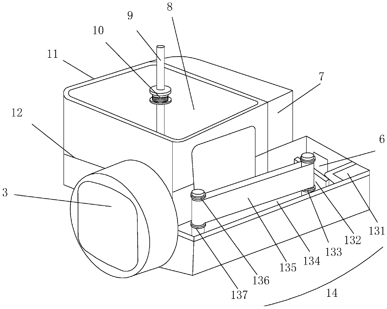
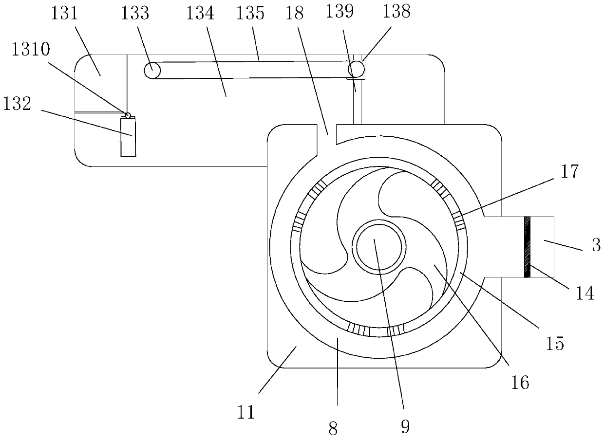
[0025] see Figure 1-Figure 7, the present invention provides a water flow control structure of a water-cooled multi-unit unit, which structure includes an external rotating shaft 1, a casing 2, a water inlet 3, a screw 4, an observation window 5, a water outlet 6, a blocking block 7, a buffer chamber 8, Rotating shaft 9, installation of fixed ring 10, inner casing 11, sealing strip 12, water flow buffer mechanism 13, filter screen 14, steel ring 15, triangular screw fan 16, screw thread 17, second water outlet 18, fixed block 19, all One end of the external rotating shaft 1 penetrates through the top of the housing 2 and is mechanically connected to the top of the rotating shaft 9. The bottom end of the rotating shaft 9 is fixed on the bottom surface of the inner wall of the inner housing 11 through a fixed block 19, and the middle of the rotating shaft 9 is fixed The fixed ring 10 is installed, and the triangular spiral fan 16 is embedded in the fixed ring 10. The triangular...
PUM
Abstract
The invention discloses a water cooling multi-connection type unit water flow control structure. The water cooling multi-connection type unit water flow control structure comprises an outer connectionrotation shaft, a shell, a water inlet, a bolt, an observation window, a water outlet, a stop block, a buffer chamber, a rotation shaft, a mounting fixing ring, an inner shell, a seal strip, a waterflow buffer mechanism, a filter net, a steel ring, a triangular spiral fan, a thread, a second water outlet and a fixing block; the water flow buffer mechanism, the triangular spiral fan, a flow limiting damping structure and a height limiting structure are arranged, the water flow can be reduced secondarily, the passing water flow is reduced, the water flow acceleration is carried out through external connection of a small motor, the water circulation flow can be directly improved, the flow limiting damping structure and an intercepting plate are arranged, the water flow inertia and the spring elastic characteristics are used for automatic flow limiting, electric control is not needed, the energy cost is increased, the height limiting structure is arranged, a movable plate is supported, the pressure borne by the spring is reduced, and the service life of the spring is directly prolonged.
Description
technical field [0001] The invention relates to a water flow control structure of a water-cooled multi-connected unit, which belongs to the field of flow control equipment. Background technique [0002] Building energy consumption has always occupied a large proportion of my country's total social energy consumption, and the energy consumption of air-conditioning systems is an important part of building energy consumption. In the air-conditioning system, the transportation energy consumption of chillers and water pumps accounts for about The energy consumption of the entire air-conditioning system is about 70%. Therefore, the research on the energy saving of the air-conditioning water system is of great significance to the work of energy saving and emission reduction in my country. For primary pumps, due to their good reliability and simple control, most of them use constant flow operation. With the maturity of frequency conversion technology and the improvement of social awar...
Claims
Application Information
Patent Timeline
Application Date:The date an application was filed.
Publication Date:The date a patent or application was officially published.
First Publication Date:The earliest publication date of a patent with the same application number.
Issue Date:Publication date of the patent grant document.
PCT Entry Date:The Entry date of PCT National Phase.
Estimated Expiry Date:The statutory expiry date of a patent right according to the Patent Law, and it is the longest term of protection that the patent right can achieve without the termination of the patent right due to other reasons(Term extension factor has been taken into account ).
Invalid Date:Actual expiry date is based on effective date or publication date of legal transaction data of invalid patent.