Novel U-shaped screw bender

A bending machine and U-shaped technology, which is applied in the field of new U-shaped screw bending machines, can solve the problems that the personal safety of operators cannot be guaranteed, the working intensity of operators is reduced, and the bending requirements cannot be met, so as to improve the overall stability , Enhanced practicability, conducive to the effect of popularization and use

Inactive Publication Date: 2018-05-15
祝莉红
View PDF0 Cites 3 Cited by
  • Summary
  • Abstract
  • Description
  • Claims
  • Application Information

AI Technical Summary

Problems solved by technology

[0002] At present, in many construction or structural connection installations, a large number of U-shaped screws need to be used. Generally, the bending production and processing of U-shaped screws is mainly through the use of straight raw materials (such as stainless steel wire, etc.) by relevant operators. Gas welding and other equipment are used to bake and bend. This production method has extremely low bending efficiency and cannot guarantee the personal safety of operators. At the same time, the quality of the finished products is not uniform; Bending requirements have brought great inconvenience to users. Although the existing U-shaped steel wire bending machines do not need to be baked for bending, most of them use the principle of leverage to cooperate with the bending disc mold to produce U-shaped screws. However, manual operation is still required, especially after the bending is completed, the curing time requires artificially holding the handle or the position of the handle for a long time, which does not reduce the working intensity of the operator very well.

Method used


Image

  • Novel U-shaped screw bender
  • Novel U-shaped screw bender
  • Novel U-shaped screw bender

Examples


Embodiment Construction

[0021] In order to further understand the content, features, and effects of the present invention, the following embodiments are listed in conjunction with the accompanying drawings.

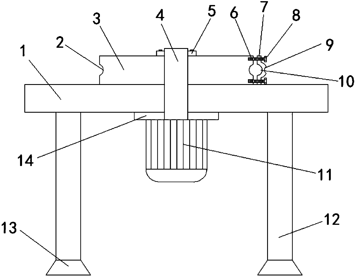
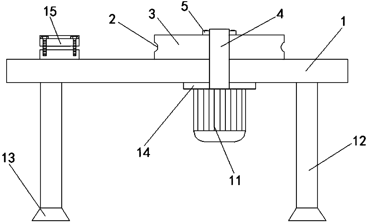
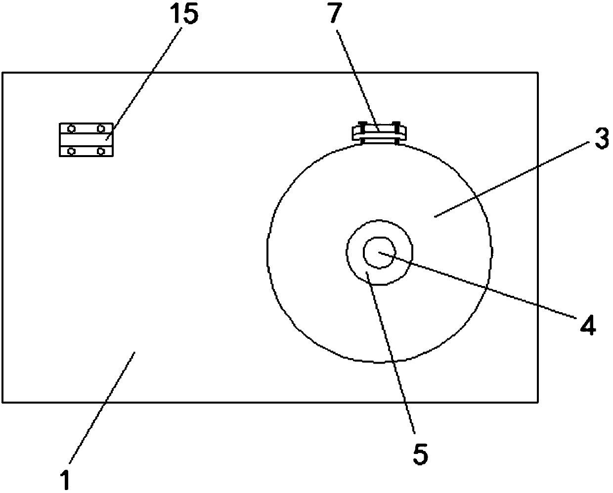
[0022] Combine below Figure 1-4 The new U-shaped screw bending machine of the present invention is described in detail: a new type of U-shaped screw bending machine, including an operating platform 1, a bending disc mold 3, a rotating shaft 4, a positioning buckle 7, a motor 11, and a support leg 12 And a limit device 15, the operating platform 1 is provided with supporting legs 12 at four corners, the bottom ends of the supporting legs 12 are fixedly connected with feet 13, and the central position of the operating platform 1 is provided with a motor 11, the motor 11 is fixedly connected to the lower surface of the operating platform 1 through the first flange 14, the output end of the motor 11 is connected with a rotating shaft 4, the rotating shaft 4 sequentially penetrates the first flange 14 ...


PUM


Abstract

The invention relates to a novel U-shaped screw bender which comprises an operation platform, a bending disc die, a rotating shaft, a positioning buckle, a motor, supporting legs and a limiting device. The supporting legs are arranged at four corners below the operation platform. The motor is arranged to drive the bending disc die to rotate to realize production of U-shaped screws, so that manpower is thoroughly liberated, working intensity of operating personnel is greatly lowered, and working efficiency is high; the machine is simple and convenient to operate, time-saving and labor-saving, and needed U-shaped screws can be obtained by only sequentially inserting raw materials into a limiting hole formed by an upper limiting groove and a lower limiting groove and a positioning hole formedby a circumferential groove and a first positioning groove, extending out a section from the positioning hole, driving the first positioning groove in the positioning buckle through a positioning bolt to tightly press the raw materials into the circumferential groove of the bending disc die, enabling the rear ends of the raw material to be positioned in the limiting groove and enabling the motorto drive the bending disc die on the rotating shaft to rotate by 180 degrees.

Description

Technical field [0001] The invention belongs to the technical field of screw processing, and particularly relates to a novel U-shaped screw bending machine. Background technique [0002] At present, in many constructions or structural connection installations, a large number of U-shaped screws need to be used. Generally, the production and processing of U-shaped screws is mainly through the use of straight raw materials (for example, stainless steel wire, etc.) by related operators. Gas welding and other equipment are roasted for bending. This production method has extremely low bending efficiency and cannot guarantee the personal safety of the operator. At the same time, the quality of the finished product is relatively uneven; in addition, it cannot meet the requirements of different models. Bending requirements have brought great inconvenience to users. Although the existing U-shaped steel wire bending machine does not need to be baked for bending, most of them use the princip...

Claims


Application Information

Patent Timeline
Patent Type & Authority Applications(China)
IPC IPC(8): B21F1/00
CPCB21F1/00
Inventor 祝莉红
Owner 祝莉红
Why Eureka
Try Eureka