
Blower tray

A technology for fans and cabinets, applied in the field of fan trays, can solve the problems of reduced efficiency of fan operation and reduced space obtained, and achieve the effects of reduced power, easy removal and replacement, and high mechanical efficiency

Active Publication Date: 2018-05-11
GOOGLE LLC
View PDF6 Cites 0 Cited by
  • Summary
  • Abstract
  • Description
  • Claims
  • Application Information

AI Technical Summary

Problems solved by technology

As a result, the resulting space within the rack for the blower fan is reduced, which in turn results in reduced efficiency in the operation of the blower fan

Method used


Image

  • Blower tray
  • Blower tray
  • Blower tray

Examples


Embodiment Construction

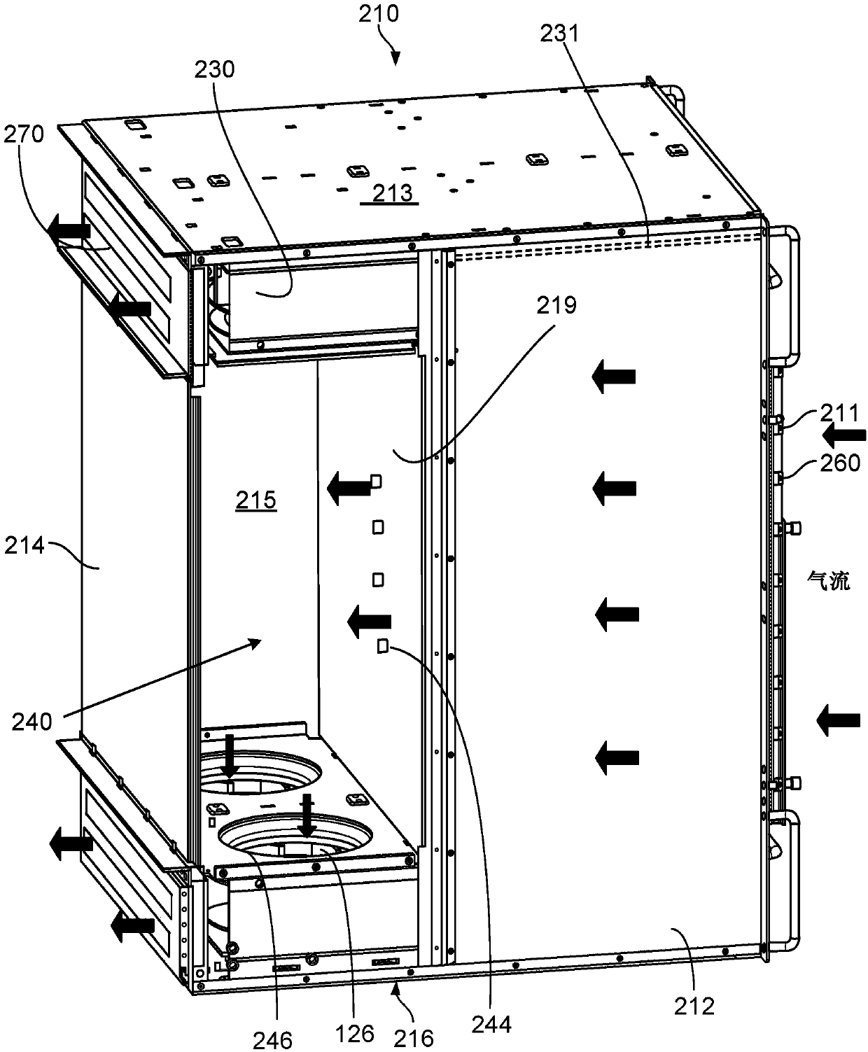
[0014] This document describes devices, systems and methods for a fan tray device that may be used with a cabinet and draws air, eg, into the cabinet and through the fan tray device. These features and additional features are described in more detail below.

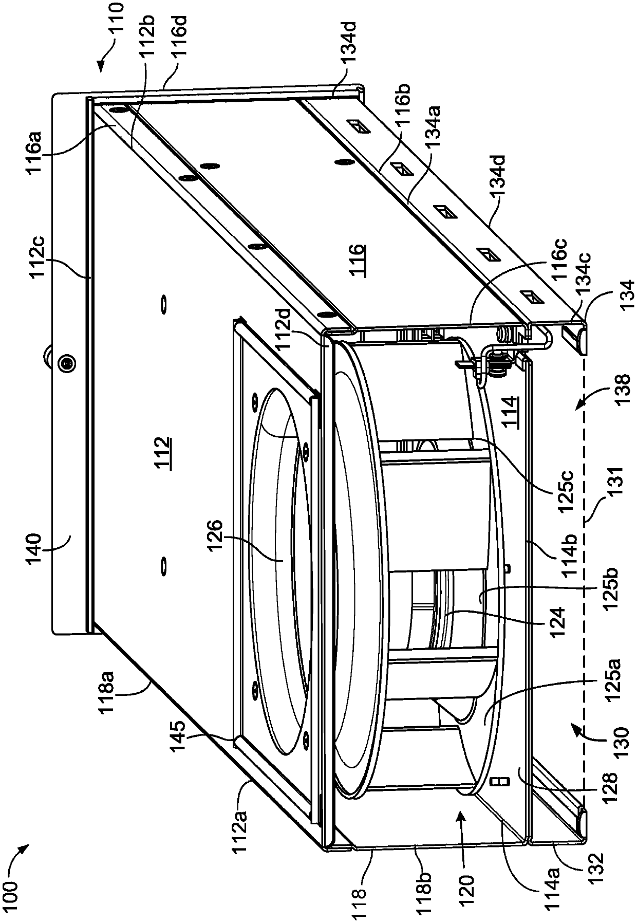
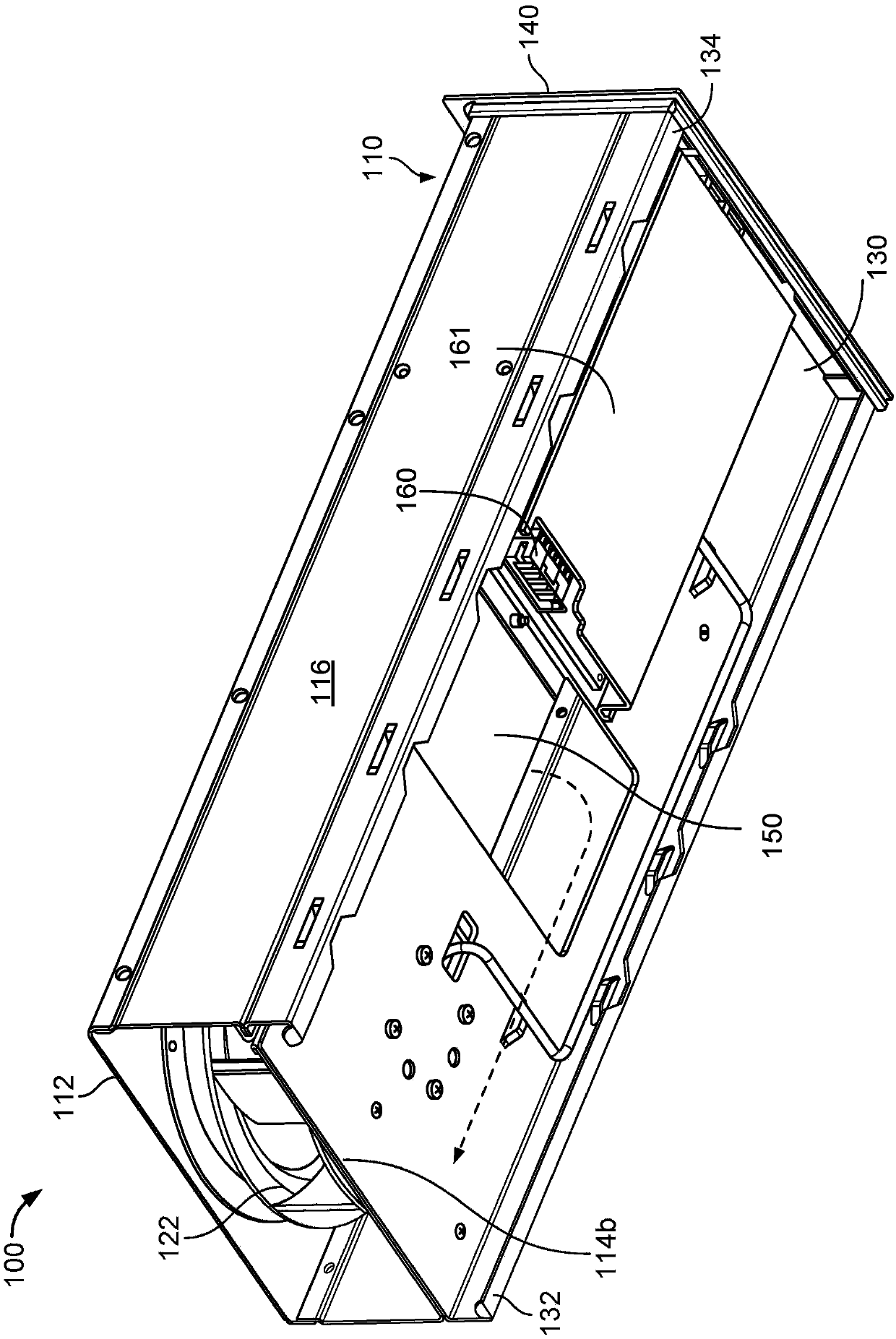
[0015] Figure 1A is a perspective view of the fan tray device 100 viewed from the rear end of the fan tray device. The fan tray apparatus 100 includes a housing 110 that includes a top surface 112 , a bottom surface 114 , a first side surface 116 , and a second side surface 118 . In the current embodiment, top surface 112 includes edges 112a, 112b, 112c, and 112d. In the current embodiment, bottom surface 114 includes edges 114a and 114b and corresponding opposing edges (not shown). First side 116 includes edges 116a, 116b, 116c, and 116d. Second side 118 includes edges 118a and 118b and corresponding opposing sides. As shown, the top surface 112 is generally parallel to the bottom surface 114 and the first side surf...


PUM


Abstract

Methods, systems, and apparatus, including a housing defining a top surface, a bottom surface, and first and second side surfaces. Also included is a first rail extending from the first side surface and a second rail extending from the second surface such that when the first and second rails are slidably engaged with a third surface. A blower device is included that is axially disposed between thetop and bottom surface, wherein a first end of the housing defines a first plenum outlet, the top surface defines a plenum inlet, the bottom surface defines a second plenum outlet that is positionedon a second side of the blower device and that fluidly couples the first plenum chamber to the second plenum chamber. Further, the second plenum chamber is formed by the first and second rails, the bottom surface and the third surface has a third plenum outlet.

Description

Background technique [0001] Cooling of computing devices (eg, computer cases and cabinets) is required for proper functioning of the computing devices. As a computer operates, heat is generated by the operating components within the computing device. Computers may have fans therein to move air around the components of the computing device to provide cooling. A fan can be operatively coupled to the plenum to draw air through the computing device to facilitate cooling. [0002] Typically computing devices are arranged to maximize the use of available space, eg in server farms. This has led to the development of high density racks with multiple processing trays. As a result, the resulting space within the rack for the blower fan is reduced, which in turn results in reduced efficiency in the operation of the blower fan. Contents of the invention [0003] This instruction manual describes the technology related to the fan tray equipment. In general, one novel aspect of the s...

Claims


Application Information

Patent Timeline
IPC IPC(8): H05K7/20G06F1/20F04D29/58F04D25/16
CPCF04D25/166F04D29/582G06F1/20H05K7/20572H05K7/20581H05K7/20736H05K7/20145F04D25/00H05K7/00
Inventor 肯尼斯·戴尔·沙乌尔苏海利·法尔斯契安罗伊·迈克尔·班浓陈盈如乔纳森·D·贝克
Owner GOOGLE LLC
Learn More