
Transmission point or beam indication method and apparatus, and transmission method and apparatus of new generation wireless communication system

A wireless communication system and transmission point technology, applied in wireless communication, synchronization device, sustainable communication technology, etc., can solve the problems of reducing system capacity, increasing network side and terminal power consumption, increasing air interface resource overhead, etc.

Active Publication Date: 2018-05-11
DATANG MOBILE COMM EQUIP CO LTD
View PDF3 Cites 17 Cited by
  • Summary
  • Abstract
  • Description
  • Claims
  • Application Information

AI Technical Summary

Problems solved by technology

[0004] However, the existing technology has at least one of the following deficiencies: under certain circumstances, this method will increase the resource overhead of the air interface and reduce the system capacity; or increase the power consumption of the network side and the terminal; or because the terminal cannot recognize TRP / Beam, it cannot Accurate channel estimation measurement and precise power control are not conducive to the improvement of signaling and data transmission reliability

Method used


Image

  • Transmission point or beam indication method and apparatus, and transmission method and apparatus of new generation wireless communication system
  • Transmission point or beam indication method and apparatus, and transmission method and apparatus of new generation wireless communication system
  • Transmission point or beam indication method and apparatus, and transmission method and apparatus of new generation wireless communication system

Examples


Embodiment 1

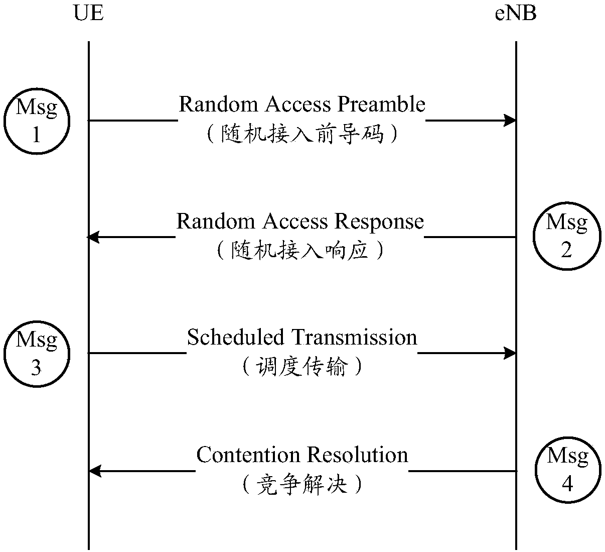
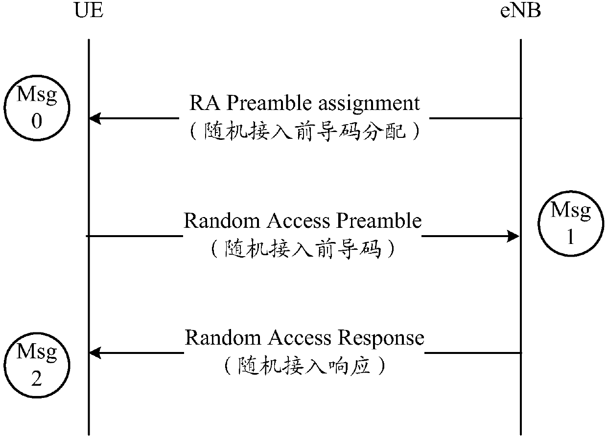
[0149] In this example, the gNB indicates the TRP / Beam accessed by the UE in the random access response, and uses the specified TRP / Beam in the subsequent random access process.

[0150] Corresponding to TRP / Beam signaling and / or data transmission mode 1, the TRP / Beam information is the TRP / Beam information corresponding to the UE sending Msg1 (preamble).

[0151] Figure 13 It is a schematic diagram of a random access process in Embodiment 1. As shown in the figure, the UE side may include the following steps:

[0152] Step 1300: Essential SI, including cell specific RACH configuration (SFNed transmission) (necessary system information, including cell-specific RACH configuration (sent in single frequency network mode, that is, nodes participating in transmission are sent synchronously with the same time-frequency resources; SFN: Single Frequency Network, single frequency network)).

[0153] The UE receives system information and obtains cell-level random access resource con...

Embodiment 2

[0165] In this example, the gNB indicates the TRP / Beam accessed by the UE in the random access response, and the UE uses the designated TRP / Beam for subsequent transmission after completing the random access.

[0166] Corresponding to TRP / Beam signaling and / or data transmission mode 1, the TRP / Beam information is the TRP / Beam information corresponding to the UE sending Msg1 (preamble). Embodiment 2 is to avoid interference caused by UE wrongly using TRP / Beam resources before the contention is resolved.

[0167] Figure 14 It is a schematic diagram of the random access process in Embodiment 2. As shown in the figure, the UE side may include the following steps:

[0168] Step 1400: Essential SI, including cell specific RACH configuration (SFNed transmission).

[0169] The UE receives system information and obtains cell-level random access resource configuration (including PRACH resources, preamble configuration, etc.), and the system information is sent synchronously by all or...

Embodiment 3

[0182] In this example, the gNB indicates all TRP / Beam information in the cell. After sending Msg1, the UE detects the TRP / Beam where it is based on all TRP / Beam information in the cell, and completes random access.

[0183] Corresponding to TRP / Beam signaling and / or data transmission mode 2, the TRP / Beam information indicates all or part of the transmission points or beam information of the cell.

[0184] Figure 15 It is a schematic diagram of the random access process in Embodiment 3. As shown in the figure, the UE side may include the following steps:

[0185] Step 1500: Essential SI, including cell specific RACH configuration (SFNed transmission).

[0186] The UE receives system information and obtains cell-level random access resource configuration (including PRACH resources, preamble configuration, etc.), and the system information is sent synchronously by all or a part of the transmission points or beams in the cell.

[0187] Step 1501: Msg1: Preamble.

[0188] The ...


PUM


Abstract

The invention discloses a transmission point or beam indication method and apparatus, and a transmission method and apparatus of a new generation wireless communication system. The transmission pointor beam indication method comprises the following steps: determining, by a network side, a transmission point or beam in a cell for providing signaling and / or data transmission for a terminal; and ina random access process, sending random access response to the terminal, wherein the random access response carries the information of the transmission point or the beam. In the random access process,the terminal receives the random access response, the random access response carries the information of the transmission point or the beam in the cell for providing the signaling and / or data transmission for the terminal; and the terminal performs TRP / Beam level transmission according to the transmission point or the beam. By adoption of the transmission point or beam indication method and apparatus disclosed by the invention, the air interface resource overhead can be reduced, and the system capacity is improved; the power consumption of the network side and the terminal is reduced; accuratechannel estimation measurement and precise power control can be achieved, and it is conducive to improving the reliability of signaling and data transmission.

Description

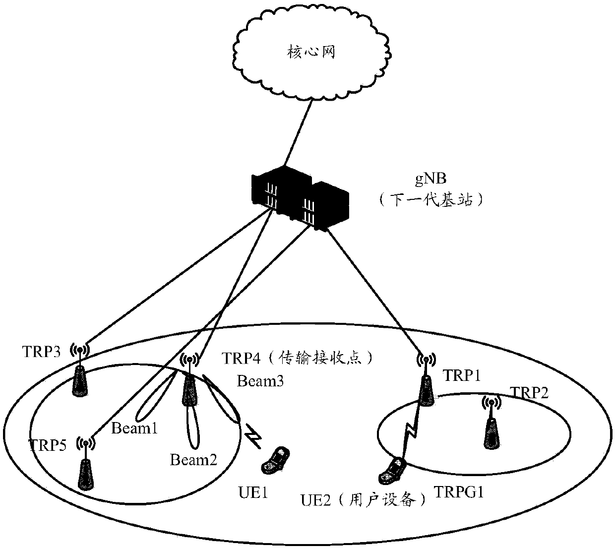
technical field [0001] The present invention relates to the technical field of wireless communication, in particular to a transmission point or beam indication, transmission method and device of a new generation wireless communication system. Background technique [0002] figure 1 It is a schematic diagram of the new generation wireless communication system architecture. The network architecture introduced in the new generation wireless communication system (called NG or 5G system) is as follows: figure 1 shown. The network side node gNB (next generation NodeB, next-generation base station) may include one or more transmission points TRP (Transmission Reception Point, transmission reception point / transmission point), and each transmission point may communicate with the terminal through a different beam (Beam). Air interface signaling and data transmission. That is, in a cell under a gNB, the TRP is a network-side transmission point that directly communicates with the term...

Claims


Application Information

Patent Timeline
IPC IPC(8): H04W16/28H04W56/00H04W74/00H04W74/08
CPCH04W16/28H04W56/001H04W74/002H04W74/0833H04W56/00H04W74/00H04W74/08Y02D30/70
Inventor 谌丽陈瑞卡
Owner DATANG MOBILE COMM EQUIP CO LTD
Learn More