
Anti-collision fire hydrant floating ball control device

A control device and a technology for tying a floating ball, which are used in water supply devices, water extraction devices, fire rescue and other directions, can solve the problems of no longer use, cumbersome operation, and high maintenance costs, and achieve low use and maintenance costs and simple operation. , The effect of low maintenance cost

Pending Publication Date: 2018-05-11
CHENZHOU XIONGJIAN MACHINE TOOL CASTING
View PDF3 Cites 3 Cited by
  • Summary
  • Abstract
  • Description
  • Claims
  • Application Information

AI Technical Summary

Problems solved by technology

[0004] Since one end of the ejector rod is in contact with the valve floating ball, the other end extends out of the fire hydrant cap through the anti-collision joint and the bolt body and is threadedly connected with the fire hydrant cap, that is, the ejector rod is a whole. When the anti-collision joint is broken , the threaded connection between the ejector rod and the fire hydrant cap cannot be separated, the ejector rod is also bent and deformed by the impact, and cannot be used anymore. When replacing the anti-collision joint, the ejector rod needs to be replaced at the same time, which is cumbersome to operate and high in maintenance costs

Method used


Image

  • Anti-collision fire hydrant floating ball control device
  • Anti-collision fire hydrant floating ball control device

Examples


Embodiment Construction

[0012] The present invention will be described in detail below in conjunction with the drawings and specific embodiments:

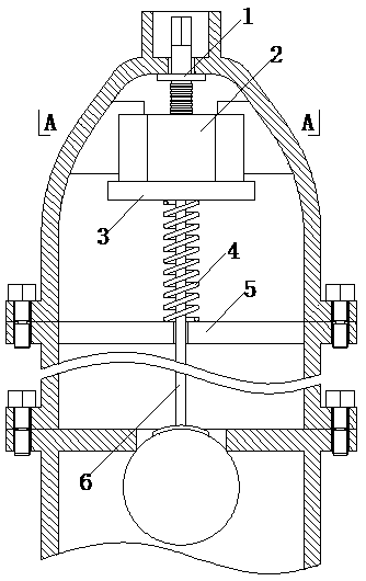
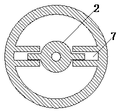
[0013] Such as figure 1 , figure 2 As shown, the anti-collision fire hydrant float control device of the present invention includes a fire hydrant cap and a hydrant body. It also includes a rotating rod, a lifting top 2, a pressing block 3, a pressing rod 6 and a spring 4. The top of the fire hydrant cap is provided with a hole through which a rotating rod passes. The bolt body and the fire hydrant cap are connected by a flange. A protruding ring 5 is provided in the top of the bolt body or the bottom of the fire hydrant cap. The top of the rotating rod is provided with a wrench interface for turning the rotating rod with a wrench. A flange ring 1 is provided under the rotating rod wrench interface. The bottom end of the rotating rod is provided with a thread, the top of the rotating rod extends out of the hole on the top of the fire hydrant cap, and t...


PUM


Abstract

The invention discloses an anti-collision fire hydrant floating ball control device which comprises a fire hydrant cap and a hydrant body and further comprises a rotation rod, a lift jack, a press block, a press rod and a spring; a bulge ring is arranged in the top of the hydrant body or the bottom of the fire hydrant cap; a spanner connector is arranged at the top end of the rotation rod; a bulgering is arranged below the spanner connector of the rotation rod; threads are formed in the bottom end of the rotation rod whose top end stretches out of a hole in the top of the fire hydrant cap andthe bulge ring seals the hole in the top of the fire hydrant cap; a thread hole which is matched with the bottom end of the rotation rod is formed in the lift jack and is in thread connection with the bottom end of the rotation rod; the press block is located below the lift jack and is in contact connection with the lift jack; the top end of the press rod is in contact connection or fixed connection with the bottom of the press block, and the bottom end of the press rod is in contact connection with a floating ball; the press rod is sleeved with the spring, the top end of the spring is in fixed connection with the press rod or in contact connection with the bottom of the press block, and the bottom end of the spring is in contact connection with the bulge ring in the top of the hydrant body or the bottom of the fire hydrant cap.

Description

Technical field [0001] The invention relates to a fire fighting device, in particular to a floating ball control device for an anti-collision fire hydrant. Background technique [0002] Fire hydrants are also called fire hydrants. There are ground fire hydrants and wall fire hydrants, etc., which are used to supply water for fire trucks or connect water pipes for fire fighting. The traditional above-ground fire hydrant includes a plug body and a valve body. The plug body is connected to the valve body. The valve body is connected to the underground waterway. The plug body is provided with an ejector rod. The valve body is provided with a valve float. The valve float is controlled to open by rotating the control ejector rod on the top of the cap. , The valve body supplies water to the plug body, and the plug body supplies water from the side water supply port. [0003] The top rotation control ejector rod of the currently used anti-collision fire hydrants is to connect one end of t...

Claims


Application Information

Patent Timeline
Patent Type & Authority Applications(China)
IPC IPC(8): E03B9/02
CPCE03B9/02
Inventor 肖建兵
Owner CHENZHOU XIONGJIAN MACHINE TOOL CASTING
Learn More