
Aquatic feed feeding device

An aquatic feed and feeding tube technology, applied in fish farming, application, climate change adaptation and other directions, can solve the problems of inconvenient feeding, increased oxygen, high labor intensity, etc., and achieves easy throwing, wide angle and good effect. Effect

Inactive Publication Date: 2018-05-11
张志通
View PDF0 Cites 9 Cited by
  • Summary
  • Abstract
  • Description
  • Claims
  • Application Information

AI Technical Summary

Problems solved by technology

[0002] During aquaculture, it is necessary to feed the aquatic animals to be eaten by the aquatic animals. Usually, it is manually fed, which is time-consuming and labor-intensive. Larger fish ponds will also increase the labor intensity of the workers and reduce the efficiency of feed feeding.
There are also some feeding devices, but their functions are single and the structure is simple. When the feeding device is in use, it will be inconvenient to feed and the feed cannot be continuously replenished.
The falling of the feed is too fast and too much, which will cause the blockage of the feeding pipe
The feed cannot be thrown and fed, and the feeding is uneven
Feeding does not add oxygen to the water
The range of feeding and oxygenation is too small, which affects the feeding of aquatic animals

Method used


Image

  • Aquatic feed feeding device
  • Aquatic feed feeding device
  • Aquatic feed feeding device

Examples


Embodiment Construction

[0018] Below in conjunction with accompanying drawing and specific embodiment the present invention is described in further detail:

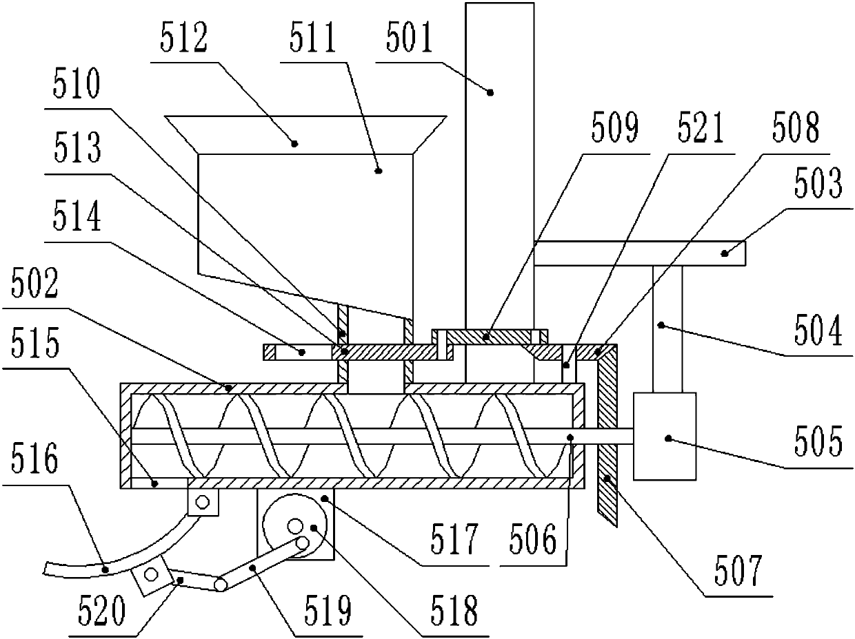
[0019] Such as figure 1 , figure 2 , image 3 , Figure 4 , Figure 5 As shown, a kind of aquatic feed feeding device comprises a slide bar 1, the slide bar 1 is covered with a slide block 2 and is slidably connected with it, the lower end of the slide block 2 is fitted with a rotating plate 8, and the rotating plate 8. An annular rotating disk 3 is fixed on the upper end. The section of the annular rotating disk 3 is "T" shaped. The lower end of the slider 2 is provided with a chute matching the annular rotating disk 3. The annular rotating disk 3 The slider 2 is embedded with a motor A4, the output shaft of the motor A4 passes through the rotating plate 8 and is fixed to it, and the thrower 5 and the aerator are arranged under the rotating plate 8 6. The thrower 5 also includes a connecting rod 501, the upper end of which is fixed to the...


PUM


Abstract

The invention discloses an aquatic feed feeding device. The device comprises a sliding rod, a sliding block is arranged on the sliding rod, a rotating plate is arranged on the lower portion of the sliding block, and a motor A is arranged in the sliding block; a material throwing device and an oxygen increasing machine are arranged on the lower portion of the rotating plate, the material throwing device comprises a connecting rod, a barrel A is arranged on the lower portion of the connecting rod, a transverse plate A is arranged on the right side of the connecting rod, a fixed rod is arranged on the lower portion of the transverse plate A, a motor B is arranged on the lower portion of the fixed rod, an auger A is fixed to the motor B, a discharge tube is arranged on the barrel A, a materialstorage box is arranged on the discharge tube, a feed inlet is formed in the material storage box, a transverse plate B is arranged on the discharge tube, a discharge opening is formed in the transverse plate B, a rocker A is arranged on the transverse plate B, a rotating shaft is arranged on the barrel A, a bevel gear B is arranged on the rotating shaft, a bevel gear A is arranged on the motor B, an opening A is formed in the lower portion of the barrel A, an arc-shaped plate is arranged below the opening A, the motor B is arranged on the lower portion of the barrel A, a disc A is arranged on the motor B, a crank A is arranged on the disc A, and a rocker B is arranged on the crank A; the oxygen increasing machine comprises a compressed air bag. Accordingly, feeding is convenient, and thefeeding effect is good.

Description

technical field [0001] The invention relates to the field of aquaculture, in particular to an aquatic feed feeding device. Background technique [0002] During aquaculture, it is necessary to put feed on the aquatic animals for the aquatic animals to eat. Usually, it is manually fed, which is time-consuming and laborious. Larger fish ponds will also increase the labor intensity of the workers and reduce the efficiency of feed feeding. There are also some feeding devices, but their functions are single and the structure is simple. When the feeding device is in use, feeding will be inconvenient, and the feed cannot be continuously replenished. If the feed falls too fast and too much, it will cause the blockage of the feed pipe. The feed cannot be thrown and fed, and the feed is uneven. Feeding does not add oxygen to the water. The range of feeding and oxygenation is too small, which affects the feeding of aquatic animals. Contents of the invention [0003] In order to so...

Claims


Application Information

Patent Timeline
Patent Type & Authority Applications(China)
IPC IPC(8): A01K61/80A01K63/04
CPCA01K61/80A01K63/042Y02A40/81
Inventor 张志通
Owner 张志通
Learn More