Electromagnetic damper

An electromagnetic damper and damper technology, which is applied in the directions of instruments, navigation, surveying and navigation, etc., can solve the problems of extended north-seeking time of gyroscopes, limitation of gyroscope start-stop times, jitter, etc., so as to shorten the north-seeking time and reduce the swing Too large to speed up the north-seeking effect

Inactive Publication Date: 2018-05-08
TIANJIN NAVIGATION INSTR RES INST
View PDF5 Cites 3 Cited by
  • Summary
  • Abstract
  • Description
  • Claims
  • Application Information

AI Technical Summary

Problems solved by technology

But in fact, during the lowering process of the lifting device, the gyro sensitive device may be unable to rotate the stepper motor to track the moving cursor due to excessive swing, severe vibration, and deviation from the range of the CCD to capture the moving cursor. The lowering is unsuccessful and the gyro sensitive device needs to be lifted Decentralize again until the requirements are met
This makes the north-seeking time of the gyro longer
And it is also limited by the number of times the gyro starts and stops.

Method used


Image

  • Electromagnetic damper
  • Electromagnetic damper
  • Electromagnetic damper

Examples


Embodiment 1

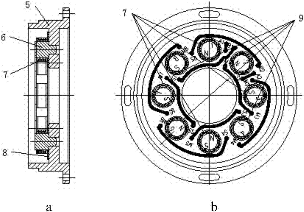
[0029] An electromagnetic damper includes a damper stator 4 , a damper rotor 1 and a magnetic shield 3 . The damper rotor is installed on the hanging wire transition axis 2 at the bottom of the gyro sensitive device, and its geometric center coincides with the hanging wire transition axis. The damper stator 4 is arranged coaxially with the damper rotor 1 and is located below the damper rotor 1 , and the damper stator 4 is fixedly connected with the housing of the gyro sensitive device. The layout of the stator and rotor structure of the damper is radially centered up and down, and there is a gap between the stator and rotor of the damper, and the gap is set as h. In order to prevent external magnetic field interference, a magnetic shield is provided outside the damper stator 4 and the damper rotor 1 .

[0030] Such as figure 2 As shown, the damper stator is a disc with eight stator cores 6 with coils, and the eight stator cores 6 are evenly distributed on the stator magneti...

Embodiment 2

[0037] Its working principle, structure and figure 1 The structure is consistent. It's just different in layout.

[0038] Such as Figure 4As shown, an electromagnetic damper includes a damper stator 14 , a damper rotor 12 and a magnetic shield 3 . The damper rotor 12 is installed on the hanging wire transition shaft 2 at the bottom of the gyro sensitive device, and its geometric center coincides with the hanging wire transition shaft 2 . The damper stator 14 is arranged coaxially with the damper rotor 12 and is located outside the damper rotor 12 , and the damper stator 14 is fixedly connected with the casing of the gyro sensitive device. The layout of the stator and rotor structure of the damper is radially centered up and down, and there is a gap h between the stator and rotor of the damper. In order to prevent interference from an external magnetic field, a magnetic shield is provided outside the damper stator 14 and the damper rotor 12 .

[0039] The damper rotor 12 ...


PUM


Abstract

The invention relates to an electromagnetic damper. The damper comprises a damper stator, a damper rotor and a magnetic shielding cover. According to the electromagnetic damper, the damper rotor is installed on a gyro sensor device, the damper stator is installed at the corresponding position of the rotor, the stator is fixedly connected with a shell body, and an air-gap field is generated by electrifying a stator coil to generate electromagnetic attraction to the rotor, so that a magnetic core of the rotor moves towards the magnetic core of the stator to achieve vertical radial centering of the gyro sensor device. The problem that the gyro sensor device needs to be held and lowered again due to the fact that the swing range is excessive large, the jittering is serious, and the gyro sensordevice movement cursor trajectory is captured deviating from CCD in a lowering process of the gyro sensor device is solved. The electromagnetic damper has the advantages that the gyro sensor device can be lowered successfully at a time to speed up north seeking.

Description

technical field [0001] The invention relates to the technical field of gyro theodolite, in particular to an electromagnetic damper installed at the bottom of the gyro sensitive device of the gyro theodolite. Some measures taken by the electromagnetic damper to improve the radial centering of the sensitive part of the gyro are suitable for the automatic north-seeking system of the gyro and the system that needs to hang the vertical radial centering of the sensitive device. Background technique [0002] The gyro automatic north-seeking system is a completely autonomous orientation system. Its autonomy and high precision are widely used in military targeting and positioning, ship manufacturing, mine oil exploitation and other orientation and measurement fields. [0003] Gyro theodolite is a kind of automatic north-finding system. It is based on the hanging wire suspension mechanical rotor gyro sensitive device as the core. Under the influence of the earth's rotation, the fix...

Claims


Application Information

Patent Timeline
Patent Type & Authority Applications(China)
IPC IPC(8): G01C25/00G01C21/18G01C21/16
CPCG01C21/165G01C21/18G01C25/005
Inventor 刘晓东聂鲁燕朱学毅吴畏侯文超
Owner TIANJIN NAVIGATION INSTR RES INST
Why Eureka
Try Eureka