
Piston mounting structure for forklift portal inclined oil cylinder

A technology for tilting oil cylinders and forklift masts. It is applied in the direction of lifting devices and fluid pressure actuating devices. It can solve the problem of coaxiality difference between the seal groove and the piston rod and the inner hole of the cylinder barrel, which affects the sealing performance of the seal and parts. and the difficulty of structural design, etc., to achieve the effect of compact structure, convenient maintenance and replacement, and small footprint

Pending Publication Date: 2018-05-08
BENGBU YELI MACHINERY
View PDF10 Cites 0 Cited by
  • Summary
  • Abstract
  • Description
  • Claims
  • Application Information

AI Technical Summary

Problems solved by technology

[0004] This structure mainly has the following disadvantages: 1. There is a problem of back pressure before the two U-shaped rings in the structure for a long time, which is difficult to eliminate. During the long-term reciprocating operation of the oil cylinder, the existence of back pressure will affect the sealing performance of the seal, and instantly The back pressure will burn the seal
2. At the same time, the "back-to-back" structural space accounts for a large proportion, and the piston structure composed of a support ring and two U rings is relatively wide. For the overall design of the oil cylinder, it brings design difficulties to other parts and structures
3. In the common structure, the piston and the piston rod are connected by welding. After welding, there is a problem of poor coaxiality between the seal groove and the piston rod and the inner hole of the cylinder barrel. This problem is difficult to eliminate.

Method used


Image

  • Piston mounting structure for forklift portal inclined oil cylinder

Examples


Embodiment Construction

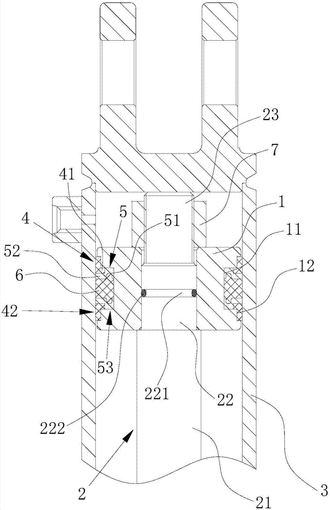
[0023] see figure 1 , the installation structure includes a piston 1, a piston rod 2 and a cylinder 3, the piston 1 is arranged on the piston rod 2, and the piston 1 and the piston rod 2 move axially in the cylinder 3;

[0024] The outer wall of the piston 1 is provided with a first annular groove 11 and a second annular groove 12 which communicate with the inside and outside and whose groove width increases;

[0025] The guide cylinder 4, protection cylinder 5, first sealing ring 6, another protection cylinder 5, and another guide cylinder 4, which are stacked sequentially from bottom to top and socketed with the piston 1, are filled in the piston 1 and the cylinder. between 3;

[0026] The structures and specifications of the guide cylinder 4 and the other guide cylinder 42 are respectively the same, and both are arranged symmetrically with respect to the first sealing ring 6;

[0027] The structures and specifications of the protection cylinder 5 and another protection cy...


PUM


Abstract

Disclosed is a piston mounting structure for a forklift portal inclined oil cylinder. The piston mounting structure comprises a piston, a piston rod and a cylinder barrel; the piston is arranged on the piston rod; the piston and the piston rod axially move in the cylinder barrel; a first annular groove and a second annular groove which are in internal-external communication and are gradually increased in groove width are circumferentially formed in the outer wall of the piston; a guiding cylinder, a protective cylinder, a first sealing ring, another protective cylinder and another guiding cylinder which are sequentially connected in a sleeved mode from bottom to top and are connected with the piston in a sleeved mode fill between the piston and the cylinder barrel; the guiding cylinder andanother guiding cylinder are the same in specification, and the protective cylinder and another protective cylinder are the same in specification; and the guiding cylinders are in sliding fit with the cylinder barrel, the first sealing ring can completely fill in a cavity among the piston, the two protective cylinders and the cylinder barrel on the basis of the self shape, specification and sizeof the first sealing ring, and the first sealing ring is in sliding fit with the cylinder barrel. The protective cylinders, the guiding cylinders and the first sealing ring are of an integrated structure, the structure is compact, the occupied space is small, and the sealing performance is excellent.

Description

technical field [0001] The invention relates to a piston installation structure for a forklift mast tilting oil cylinder. Background technique [0002] In order to quickly and conveniently fork the goods, the mast needs to be tilted forward; when picking up the goods, in order to prevent the goods from falling, the mast needs to be tilted backward to ensure the stability of the goods. The front and rear tilting of the mast needs to be completed by the tilting cylinder. For some forklift cylinders, in order to stabilize the whole vehicle or have a good appearance, the inclined cylinder requires a larger front and rear inclination angle, that is, a larger stroke requirement and a shorter installation length requirement. [0003] Usually the main structural components of forklift tilt cylinder are earrings, piston rod, guide sleeve, piston, cylinder bottom and cylinder body. The sealing structure of the piston mainly adopts the "back-to-back" sealing form, that is, the struct...

Claims


Application Information

Patent Timeline
Patent Type & Authority Applications(China)
IPC IPC(8): F15B15/14F15B15/20B66F9/22
CPCF15B15/1447F15B15/1452B66F9/22
Inventor 徐龙朱琼杰刘强强郭晛张红霞杨民正李钱宇李志红孔园园
Owner BENGBU YELI MACHINERY
Learn More