A tubular water turbine guide vane support adjustment device

A technology of tubular water turbines and regulating devices, which is applied in the direction of reaction engines, mechanical equipment, and hydroelectric power generation. The difficulty of installation and the effect of preventing stuck

Active Publication Date: 2018-11-27
DONGFANG ELECTRIC MACHINERY
View PDF5 Cites 0 Cited by
  • Summary
  • Abstract
  • Description
  • Claims
  • Application Information

AI Technical Summary

Problems solved by technology

In this solution, due to the influence of the coaxiality deviation of the inner and outer ring shaft holes of the guide vane, the double-sleeve structure will easily lead to inflexible movement of the guide vane, or even jamming, and the sleeve is easy to wear and has a short service life.
The shaft sleeve and seal at the inner end of the guide vane are arranged in the guide vane body, which is inconvenient to replace, and may even cause damage to the guide vane body due to the replacement of the shaft sleeve, increasing the maintenance workload and cycle
Moreover, the adjustment gasket structure needs to be processed on site, and it cannot meet the needs of secondary adjustment of the guide vane end face clearance after hoisting and deformation. It can be seen that this structure increases the workload of site adjustment and has poor adaptability.

Method used


Image

  • A tubular water turbine guide vane support adjustment device
  • A tubular water turbine guide vane support adjustment device
  • A tubular water turbine guide vane support adjustment device

Examples


Embodiment Construction

[0021] Below in conjunction with accompanying drawing, the present invention is described in detail.

[0022] In order to make the object, technical solution and advantages of the present invention clearer, the present invention will be further described in detail below in conjunction with the accompanying drawings and embodiments. It should be understood that the specific embodiments described here are only used to explain the present invention, not to limit the present invention.

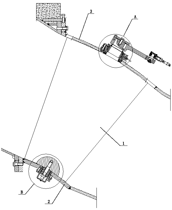
[0023] Such as figure 1 As shown, a tubular turbine guide vane support adjustment device includes a guide vane 1 and a guide vane inner ring 2 and a guide vane outer ring 3 arranged at both ends of the guide vane 1. The shaft seat assembly is connected with the inner ring 2 of the guide vane and the outer ring 3 of the guide vane.

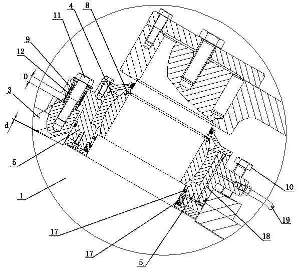
[0024] Such as figure 2 As shown, the external shaft seat assembly at the outer end of the guide vane 1 includes a guide vane joint bearing 4 and a guide vane slee...


PUM


Abstract

The invention discloses a cross flow type hydraulic turbine guide vane supporting and regulation device which comprises a guide vane, a guide vane inner ring and a guide vane outer ring; the guide vane inner ring and the guide vane outer ring are arranged at the two ends of the guide vane respectively; the two ends of the guide vane are connected with the guide vane inner ring and the guide vane outer ring through external shaft base assemblies respectively; the external shaft base assembly of the outer end of the guide vane comprises a guide vane joint bearing and a guide vane sleeve; and theexternal shaft base assembly of the inner end of the guide vane comprises a split type guide vane lower end shaft and a guide vane lower supporting seat. By adopting the cross flow type hydraulic turbine guide vane supporting and regulation device provided by the invention, through the structure design of the external shaft base assemblies at the two ends of the guide vane, during maintenance, the guide vane sleeve or the guide vane lower supporting seat is singly disassembled, and maintenance and change of corresponding bearing, shaft sleeve and sealing piece can be performed, so that the maintenance and change problem in machine pits of guide vane shaft diameter sealing and guide vane upper and lower bearings can be effectively solved; by arranging the guide vane joint bearing at the guide vane shaft diameter position, a deviation quantity which can be between shaft hole processing errors, unit mounting errors, unit stress deformation and the like of the guide vane inner and outer rings and those in the design theory can be effectively compensated, so that the manufacturing and mounting difficulty is reduced, and deadlocking of the guide vane is effectively prevented.

Description

technical field [0001] The invention belongs to the technical field of water turbine design, in particular to a guide vane support adjustment device for a tubular water turbine. Background technique [0002] The tubular turbine is arranged on a horizontal shaft, and its movable guide vane is a cone-shaped structure, which adopts a double fulcrum support structure of the inner and outer rings of the guide vane. The coaxiality of the guide vane support shaft hole and the clearance of the guide vane end face are important indicators for evaluating the installation quality. It is necessary to ensure the flexible movement of the guide vane and meet the requirements for the water leakage of the guide vane. [0003] The size of the existing tubular water turbine unit is relatively large. On the one hand, the inner and outer rings of the guide vane cannot be bored at the same time due to the large size of the guide vane; on the other hand, the rigidity of the unit is relatively poo...

Claims


Application Information

Patent Timeline
Patent Type & Authority Patents(China)
IPC IPC(8): F03B3/18
CPCF03B3/183Y02E10/20
Inventor 罗远红张小军曾明富孙媛媛文树洁李新威吴晓莉李小兵代继江张少辉
Owner DONGFANG ELECTRIC MACHINERY
Why Eureka
Try Eureka