
Force reduction mechanism of winch

A winch, integrated technology, applied in the direction of the spring mechanism, mechanical equipment, transmission parts, etc., can solve the problems of huge and cumbersome structure, does not meet the operating requirements, etc., achieve small volume, optimize space utilization, and good interchangeability Effect

Pending Publication Date: 2018-05-08
JILIN UNIV
View PDF0 Cites 2 Cited by
  • Summary
  • Abstract
  • Description
  • Claims
  • Application Information

AI Technical Summary

Problems solved by technology

The design of the existing drawworks force reduction mechanism, its load capacity is inversely proportional to its volume, and the larger the mechanism that can provide the load, the larger and heavier the structure. On the contrary, the compact and small mechanism can provide the same load. The more limited; and extreme special working conditions such as polar regions or deep seas obviously require that the volume of the winch should be smaller under the premise of lifting the load, and the existing winch force reduction mechanism is obviously not suitable for operations in extreme special working conditions such as polar regions or deep seas Require

Method used


Image

  • Force reduction mechanism of winch
  • Force reduction mechanism of winch
  • Force reduction mechanism of winch

Examples


specific Embodiment approach

[0037] In order to further illustrate the technical solution of the present invention and the technical effects brought by it, in conjunction with the accompanying drawings, the specific implementation of the present invention is as follows:

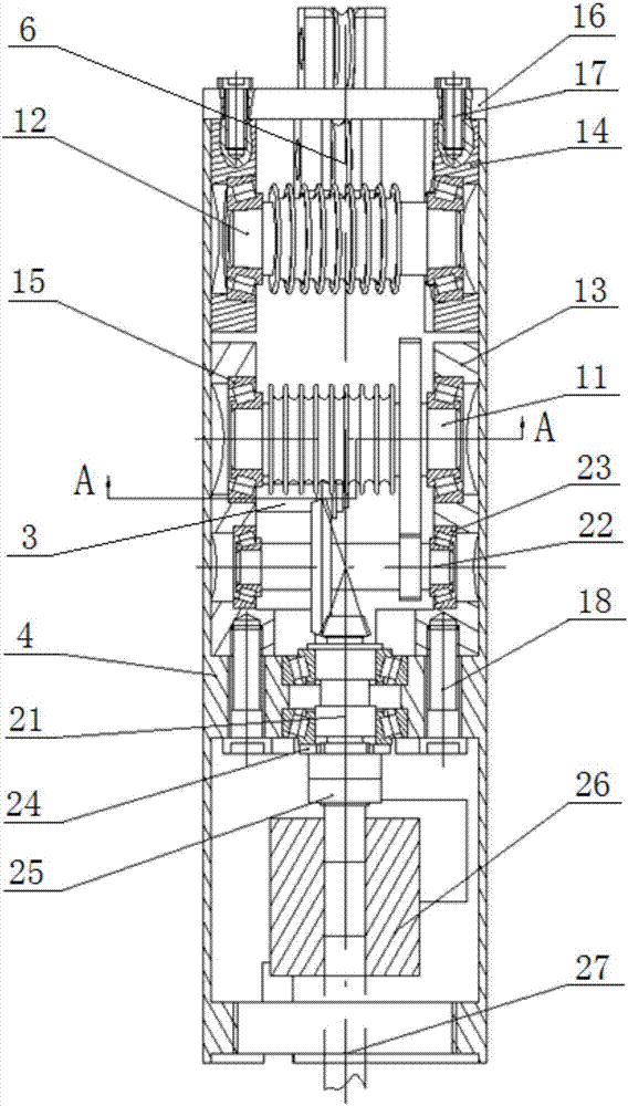
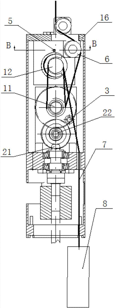
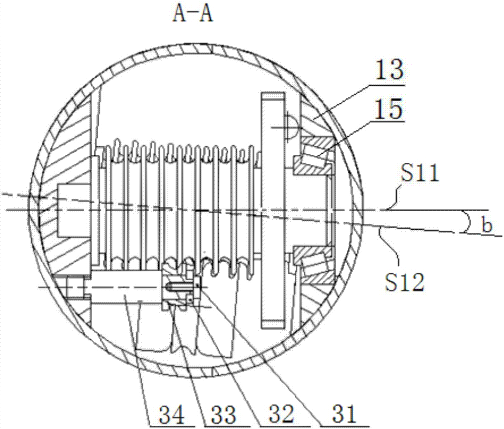
[0038] The present invention provides a thin cylindrical drawworks force reduction mechanism with small volume and large load, such as figure 1 As shown, the drawworks force reduction mechanism of the present invention is mainly composed of a driving bevel gear shaft 21, a transmission gear shaft 22, a lower sheave shaft 11, an upper sheave shaft 12, an upper guide wheel assembly 6, a lower guide wheel assembly 3, a housing 4 and Upper cover plate 16 is formed.

[0039] Described housing 4 is a cylinder shape, is provided with upper and lower two cavities, and above-mentioned transmission gear shaft 22, lower sheave shaft 11, upper sheave shaft 12, some components in upper guide wheel assembly 6 and lower guide wheel The components 3 ar...


PUM


Abstract

The invention discloses a force reduction mechanism of a winch. The force reduction mechanism of the winch is composed of an upper guide wheel assembly, a lower guide wheel assembly, a shell, an uppercover plate, a driving bevel gear shaft, a transmission gear shaft, a lower grooved wheel shaft and an upper grooved wheel shaft, wherein the driving bevel gear shaft, the transmission gear shaft, the lower grooved wheel shaft and the upper grooved wheel shaft are sequentially arranged in the shell from bottom to top and integrally machined. The middle of the driving bevel gear shaft is installedon the annular inner edge of the shell. A driving bevel gear at one end of the driving bevel gear shaft is engaged with a driven bevel gear in the middle of the transmission bevel gear shaft, and theother end of the driving bevel gear shaft is connected with a power source. A driving straight gear at the end of the transmission gear shaft is engaged with a driven straight gear at the end of thelower grooved wheel shaft. Gear grooves are formed in the middle section of the lower grooved wheel shaft and the middle section of the upper grooved wheel shaft in parallel. The upper guide wheel assembly is installed on the upper cover plate to guide in a cable along the center line of the shell and then guide the cable to the lower grooved wheel shaft; and the lower guide wheel assembly is installed below the lower grooved wheel shaft and used for guiding the cable out from the upper grooved wheel shaft to a position away from a gear drive pair. The force reduction mechanism of the winch isof a long and thin structure and small in size and can provide a large load.

Description

technical field [0001] The invention belongs to the technical field of winch structure design, in particular to a winch force reduction mechanism. Background technique [0002] A winch is a light and small lifting device that uses a drum to wind a wire rope or chain to lift or pull heavy objects, also known as a hoist. The winch can be used alone or as a component in machinery such as lifting, road construction and mine hoisting; due to its high versatility, compact structure, small size, light weight, heavy lifting, and easy use and transfer, the winch It has been widely used in material lifting or flat towing operations in construction, water conservancy projects, forestry, mines, wharves, etc.; and the winch force reduction mechanism is an important part of the winch, which ensures that the winch can operate on the basis of its small size. However, the functional requirements of large loads can still be achieved. [0003] In recent years, due to the structure and perfor...

Claims


Application Information

Patent Timeline
IPC IPC(8): B66D1/14F16H57/023F16H57/038
CPCF16H57/023F16H57/038B66D1/14
Inventor 王建华雷天龙王继新李想
Owner JILIN UNIV
Learn More