Moving arm tower crane climbing beam supporting system and using method thereof
A boom tower crane and beam support technology, which is applied in cranes, transportation and packaging, etc., can solve the problems of large amount of concrete and steel reinforcement, difficult high-altitude construction, and high safety risks, so as to improve the overall load-bearing capacity and increase the Universal applicability and the effect of reducing the amount of reinforcement
- Summary
- Abstract
- Description
- Claims
- Application Information
AI Technical Summary
Problems solved by technology
Method used
Image
Examples
Embodiment 1
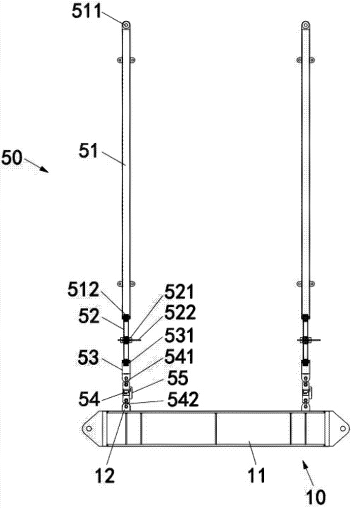
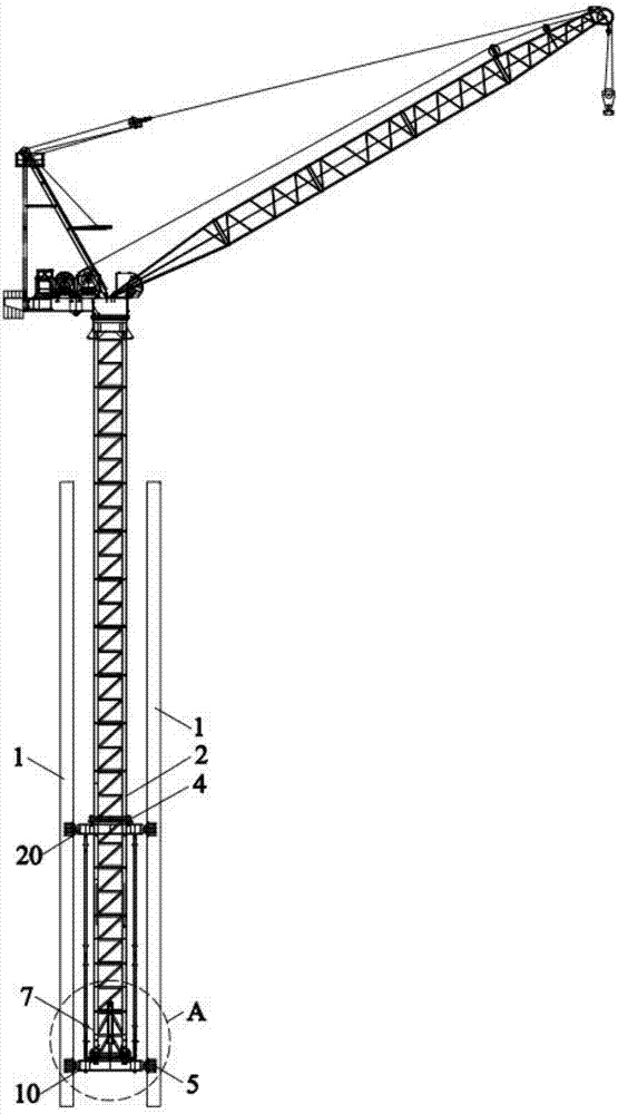
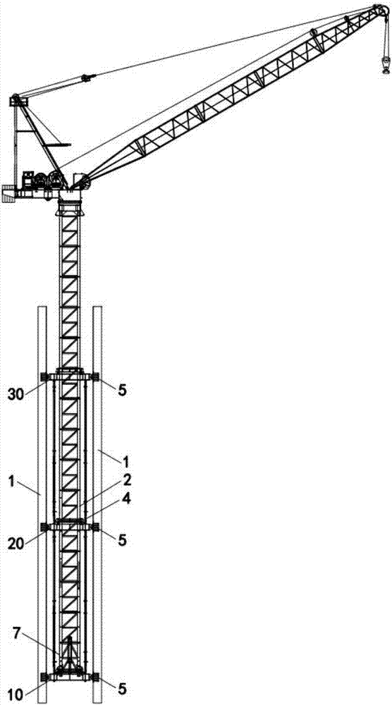
[0039] Example 1: Combining Figure 1 to Figure 7 Explain the climbing beam support system of the boom tower crane of the present invention. This embodiment takes the climbing beam support system of the inner climbing tower crane as an example to specifically illustrate its structure and connection relationship. It includes parallel and spaced beams along the climbing direction of the boom tower crane 2 The three support frames set are respectively support frame one 10, support frame two 20 and support frame three 30 from bottom to top, and are used to support the climbing jib tower crane 2; and are connected between the adjacent two support frames. Eight adjustable tie rod assemblies 50 for distributing the vertical load of the luffing jib tower crane 2;
[0040] Each support frame includes two parallel and spaced climbing beams 11, and the two ends of each climbing beam 11 are respectively connected with the embedded parts 5 bolts embedded in the shear wall 1, and are locate...
Embodiment 2
[0054] Embodiment two: different from embodiment one, as Figure 8 As shown, the adjustable tie rod assembly 50 of this embodiment includes a tie rod 51 connected sequentially from top to bottom, a flange joint 56 and an axial force servo automatic compensation device 57. The tie rod 51 is composed of a number of standard joints of the tie rod 51 connected by bolts. One end of the pull rod 51 is bolted to the top support frame, the other end of the tie rod 51 is bolted to the axial force servo automatic compensation device 57 through the flange joint 56, and the other end of the axial force servo automatic compensation device 57 is connected to the lower support frame through a ring buckle; Such as Figure 9 As shown, the axial force servo automatic compensation device 57 includes a hydraulic cylinder 571, a support seat 572, a push rod 573, at least two support frames 574, at least two locking blocks 577, at least two self-locking cylinders 576, and a PLC control unit (not s...
Embodiment 3
[0057] Example Three: Combining Figure 9 to Figure 12 The climbing beam support system of the boom tower crane of the present invention and its use method are described. The boom tower crane 2 of this embodiment is an external tower crane, that is, the three support frames are all fixed to the shear wall 1 on the same side. The frame includes two sets of triangular supports arranged in parallel and at intervals. Each triangular support is composed of two climbing beams 11 arranged at an angle and fixedly connected. Part 5 is connected by bolts, and other structures and usage methods of the climbing beam support system of the boom tower crane are the same as those in Embodiment 1 or Embodiment 2, and will not be repeated here. Therefore, the climbing beam support system of the boom tower crane of the present invention and its use method are suitable for various forms of boom tower cranes such as internal climbing and external attachment, and can be used in different forms of b...
PUM
 Abstract
Description
Claims
Application Information
 - R&D Engineer
- R&D Manager
- IP Professional
- Industry Leading Data Capabilities
- Powerful AI technology
- Patent DNA Extraction
Browse by: Latest US Patents, China's latest patents, Technical Efficacy Thesaurus, Application Domain, Technology Topic, Popular Technical Reports.
© 2024 PatSnap. All rights reserved.Legal|Privacy policy|Modern Slavery Act Transparency Statement|Sitemap|About US| Contact US: help@patsnap.com


