Novel spinning wire winding device

A winding device, a new type of technology, applied in the directions of transportation and packaging, conveying filamentous materials, thin material processing, etc., can solve the problems of affecting the winding effect, increasing labor costs, and single structure, so as to improve the smoothness and stability , Improve the working speed and improve the effect of uniformity

Inactive Publication Date: 2018-05-08
CIXI QICHENG MACHINERY TECH CO LTD
View PDF0 Cites 1 Cited by
  • Summary
  • Abstract
  • Description
  • Claims
  • Application Information

AI Technical Summary

Problems solved by technology

[0002] Textile production, processing and manufacturing requires a lot of auxiliary equipment. Auxiliary equipment is also an indispensable tool in production. For example, textile winding machines are one of the most important textile machinery and equipment in modern textile enterprises. Winding machines It is to wind semi-finished products or finished products into a certain form, so as to facilitate storage, transportation and processing in the next process. The current winding equipment generally has a single structure, poor functionality, and is not convenient for users to use, causing great harm to users. It is difficult, and it will lead to uneven winding during winding, which will affect the good winding effect. In the prior art, manual adjustment is generally used, which increases labor costs and improves economic costs.

Method used


Image

  • Novel spinning wire winding device
  • Novel spinning wire winding device
  • Novel spinning wire winding device

Examples


Embodiment Construction

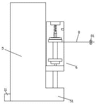
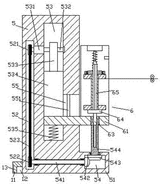
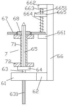
[0023] Such as Figure 1-Figure 6 As shown, a new type of textile winding device of the present invention includes a body 5 and a guide wheel 81 arranged symmetrically up and down on the right side of the body 5 , and a boss portion 51 is provided at the bottom of the right end surface of the body 5 A winding mechanism 6 is provided above the boss portion 51, and the winding mechanism 6 includes a bottom plate 61 extending left and right, a connecting block 62 fixed on the right rear side of the bottom plate 61, and a connecting block fixed on the connecting block. 62, the straight plate 66 extending upwards at the rear end and the winding base 64 above the bottom plate 61, the bottom of the winding base 64 is fixed with a first rotating shaft 63, and the bottom of the first rotating shaft 63 runs through The bottom plate 61 is connected in a rotational fit, the bottom of the first rotating shaft 63 is fixed with an external spline shaft 631 extending downward, the top of the ...


PUM


Abstract

The invention discloses a novel spinning wire winding device. The novel spinning wire winding device comprises a machine body, and guide wheels arranged on the right side of the machine body and symmetrically arranged up and down; a boss part is arranged at the bottom of the right side end surface of the machine body; a wire winding mechanism is arranged above the boss part; the wire winding mechanism comprises a baseplate extending left and right, a connecting block fixed on the back side of the right side of the baseplate, a straight plate fixed at the back side end of the connecting block and upwards extending, and a wire winding base arranged above the baseplate; a first rotating shaft is fixedly arranged at the bottom of the wire winding base; the bottom of the first rotating shaft penetrates through the baseplate for rotary cooperating connection; an outer spline shaft downwards extending is fixedly arranged at the bottom of the first rotating shaft; a single key shaft is fixedlyarranged at the top of the wire winding base; a first transmission cavity is formed in the boss part; and an inner spline rotating shaft extending to the upper and lower sides is in rotary cooperating connection into the inner top wall of the first transmission cavity. The novel spinning wire winding device is simple in structure, realizes automatic control of up-down movable wire winding work, improves the wire winding uniformity, realizes quick disassembly of bobbins, and improves the wire winding stability.

Description

technical field [0001] The invention relates to the technical field of textile machinery, in particular to a novel textile winding device. Background technique [0002] Textile production, processing and manufacturing requires a lot of auxiliary equipment. Auxiliary equipment is also an indispensable tool in production. For example, textile winding machines are one of the most important textile machinery and equipment in modern textile enterprises. Winding machines It is to wind semi-finished products or finished products into a certain form, so as to facilitate storage, transportation and processing in the next process. The current winding equipment generally has a single structure, poor functionality, and is not convenient for users to use, causing great harm to users. It is difficult, and it will lead to uneven winding during winding, which will affect the good winding effect. In the prior art, manual adjustment is generally used, which increases labor costs and improves ...

Claims


Application Information

Patent Timeline
IPC IPC(8): B65H57/14B65H75/14B65H54/44B65H54/28B65H67/04B65H54/54B65H54/74
CPCB65H57/14B65H54/28B65H54/44B65H54/543B65H54/74B65H67/0411B65H75/14B65H2701/31
Inventor 黄雪锋冯斌斌
Owner CIXI QICHENG MACHINERY TECH CO LTD
Why Eureka
Try Eureka