Graphite film roll fixture and technology for producing graphite film roll by using same

A technology of graphite film and jig, applied in the direction of winding strips, inorganic chemistry, non-metallic elements, etc., can solve the problems of shrinkage of transformation area, poor quality of output, uneven heat transfer, etc., and achieve the improvement of thermal diffusivity, Coil quality is good and the effect of ensuring uniformity

Pending Publication Date: 2018-05-04
SHANGHAI JIEYUAN ENVIRONMENTAL SCI & TECH
View PDF0 Cites 3 Cited by
  • Summary
  • Abstract
  • Description
  • Claims
  • Application Information

AI Technical Summary

Problems solved by technology

[0003] The existing process for preparing graphite film coils from PI coils has the following defects: 1. The transition area from PI to graphite film will shrink by 20%-30%
The circular core is wound and enters the carbonization furnace. During the carbonization and shrinkage of PI, the pressure between the coil near the core and the wall will increase. The hard core cannot give PI shrinkage buffer space. When the pressure exceeds When the material bears the strength, the coiled material close to the core will be damaged or broken in large quantities; 2. The PI winding method is too cumbersome, and at the same time, PET, metal strips, etc. are used to artificially set the gap between PIs to be uneven, which will cause the coiled material to be heated during carbonization Uneven coking and coking, the shrinkage shape of the obtained coils is different, which will affect the heating uniformity during graphitization. Uneven heating will lead to inconsistent shapes of graphite film coils and uneven film surfaces, which will eventually affect the calendering efficiency and calendering quality. ; 3. Use a circular core for winding, and use PET, metal strips, etc. to set the gap. This gap is generally too large and cannot be tightened naturally after carbonization. For the graphitization of the coil, the heat inside the coil Uneven transfer, poor output quality

Method used


Image

  • Graphite film roll fixture and technology for producing graphite film roll by using same
  • Graphite film roll fixture and technology for producing graphite film roll by using same
  • Graphite film roll fixture and technology for producing graphite film roll by using same

Examples


Embodiment 1

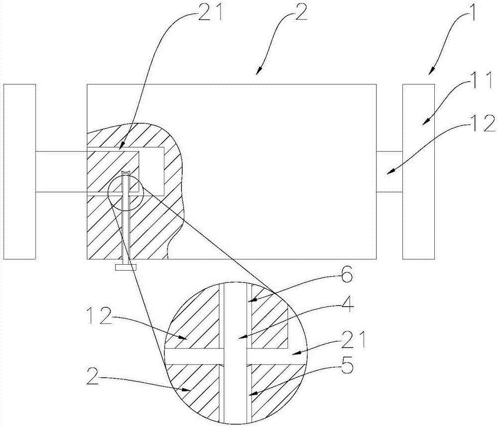
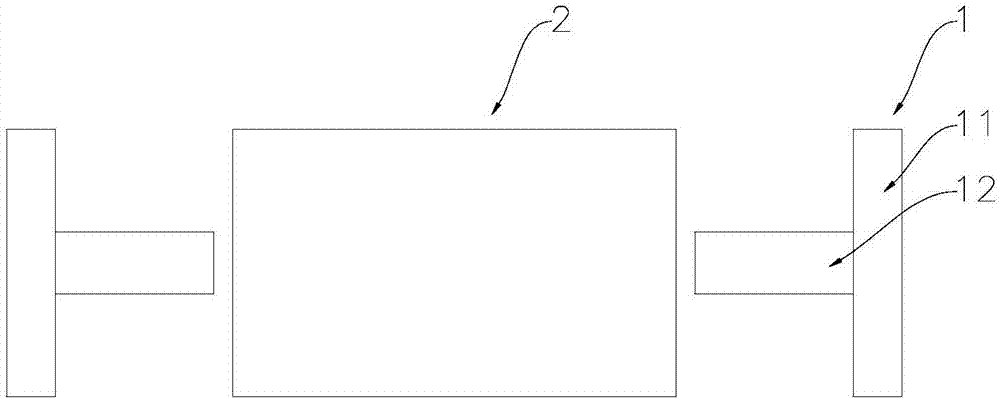
[0046] A graphite film coiled material jig. The jig is a flat square graphite jig. The jig has two winding ends 1 for winding PI film. Both of the two winding ends 1 can be stretched and contracted freely. It includes a fixture body 2 and a freely retractable winding end 1. The freely retractable winding end 1 is a T-shaped winding end 1, including a horizontal section 11 and a vertical section 12 vertically fixed in the middle of the horizontal section 11. The body 2 is provided with a receiving hole 21 for facilitating the free expansion and contraction of the vertical section 12 of the T-shaped winding end 1, and the jig is also used to restrict the movement of the T-shaped winding end 1 relative to the jig body 2 when the PI film is wound. The limit pin 4 of the fixture body 2 has a fixture body limit hole 5, the vertical section 12 is provided with a vertical section limit hole 6, and the limit pin 4 passes through the fixture body limit hole 5 and the vertical section limi...


PUM


Abstract

The invention relates to the technical field of graphite film rolls, in particular to a graphite film roll fixture. The graphite film roll fixture is a flat fixture, and comprises two winding ends forwinding a PI film, wherein at least one of the winding ends is freely retractable. The invention achieves the purposes by providing the graphite film roll fixture. When PI is wound, a material otherthan the PI is not required to be clamped in the middle of a roll any longer and winding is performed in one step, so that the PI winding efficiency is improved; the graphite film roll fixture is a graphite fixture with a freely retractable winding core, so that the roll near the winding core is not broken by pull, and the yield of the roll is higher; the graphite film roll fixture is the graphitefixture, and in the process of PI carbonation shrinkage, the roll is always in close contact with the high-heat conductivity graphite film roll fixture, so that the roll is uniformly heated from inside to outside.

Description

Technical field [0001] The invention relates to the technical field of graphite film coils, in particular to a graphite film coil jig and a graphite film coil production process. Background technique [0002] In the process of converting PI coils into graphite coils, if the quality of the PI coil is to be equivalent to that of the sheet (the film surface is fine, smooth, and without damage), technically it is necessary to achieve uniform heating of the coil, consistent shrinkage and unobstructed defocusing. The problem is that the currently commonly used technical means is to wind the PI winding section through a circular core, and then add PET, metal strips or graphite paper in the middle to set up the defocusing space or improve the uniformity of heating. To a certain extent, this method has realized the transformation from PI coil to general quality graphite coil. [0003] The existing process for preparing graphite film coils from PI coils has the following defects: 1. The are...

Claims


Application Information

Patent Timeline
Patent Type & Authority Applications(China)
IPC IPC(8): C01B32/205B65H18/02
CPCB65H18/028
Inventor 林剑锋徐世中朱秀娟
Owner SHANGHAI JIEYUAN ENVIRONMENTAL SCI & TECH
Why Eureka
Try Eureka