Flange end face grinding device

An end face and grinding bar technology, applied in the direction of grinding drive device, grinding machine, grinding frame, etc., can solve the problem of low practicability, and achieve the effect of strong practicability, convenient operation and improving work efficiency.

Inactive Publication Date: 2018-05-04
重庆市乐珐机电有限责任公司
View PDF6 Cites 1 Cited by
  • Summary
  • Abstract
  • Description
  • Claims
  • Application Information

AI Technical Summary

Problems solved by technology

[0004] However, the above-mentioned patent still has the following defects: since the grinding head is arranged on the front end of the grinding wheel, the position of the grinding head is fixed, and it can only be used for grinding flanges of one size, which is not very practical.

Method used


Image

  • Flange end face grinding device

Examples


Embodiment Construction

[0018] The present invention will be described in further detail below by means of specific embodiments:

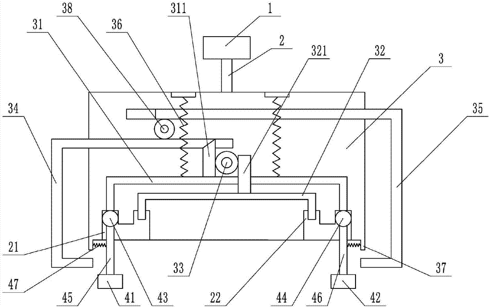
[0019] The reference signs in the drawings of the description include: motor 1, rotating shaft 2, first positioning groove 21, second positioning groove 22, rotary table 3, first fixed rod 31, first wedge rod 311, second fixed rod 32, Rack 321, first gear 33, second wedge bar 34, connecting rod 35, first spring 36, flange 37, second gear 38, first grinding bar 41, second grinding bar 42, first ball 43, The second ball 44 , the first push rod 45 , the second push rod 46 , and the second spring 47 .

[0020] Such as figure 1 As shown, the flange end face grinding device includes a motor 1, a rotating shaft 2, a rotating table 3, a first grinding bar 41 and a second grinding bar 42, the motor 1 is located above the rotating table 3, and the rotating shaft 2 is welded to the output of the motor 1 On the shaft, the lower end of the rotating shaft 2 is welded with the rotary ...


PUM


Abstract

The invention belongs to the technical field of grinding devices and particularly relates to a flange end face grinding device. The flange end face grinding device comprises a motor, a rotary shaft, arotary platform and grinding bars. The end face of the rotary platform is symmetrically provided with two cavities with openings. The two cavities are provided with two locating grooves communicatingwith each other. The bottoms of the two locating grooves are provided with through holes. Two fixed rods are further arranged in the rotary platform. The two ends of the two fixed rods penetrate through the corresponding through holes to be inserted into the two locating grooves. A first wedge bar and a rack are connected to the two fixed rods correspondingly. The first wedge bar is provided withgear teeth. The first wedge bar and the rack are both engaged with a first gear. One end of a second wedge bar and one end of a connecting rod are both slidably connected to the interior of the rotary platform. The second wedge bar abuts against the first wedge bar. The other ends of the connecting rod and the second wedge bar are both used for pushing the grinding bars to slide in the cavities.By means of the scheme, the flange end face grinding device can be suitable for grinding different sizes of flanges and suitable for grinding of batch flanges.

Description

technical field [0001] The invention belongs to the technical field of grinding devices, in particular to a flange end face grinding device. Background technique [0002] After the flange is processed, the end face needs to be polished to ensure the sealing of the flange. In order to prevent the flange surface from being worn out during grinding, people often use soft sandpaper for manual grinding, instead of using an electric polishing machine with high grinding intensity. The grinding method has low grinding efficiency and cannot meet the grinding needs of mass-produced flanges. [0003] For this reason, Chinese patent CN104325378A discloses a pull-driven flange end face grinding device, which includes a main body ring, and a grinding wheel is arranged in the main body ring; a ring of grinding heads is arranged on the front end of the grinding wheel; and a spoke plate is arranged on the inner rear side of the grinding wheel; The inner ends of the spoke plates are all fixe...

Claims


Application Information

Patent Timeline
IPC IPC(8): B24B7/16B24B41/00B24B41/02B24B47/12
CPCB24B7/16B24B41/00B24B41/02B24B47/12
Inventor 印承霜
Owner 重庆市乐珐机电有限责任公司
Why Eureka
Try Eureka