Eureka AIR delivers breakthrough ideas for toughest innovation challenges, trusted by R&D personnel around the world.

Automatic stamping device for motor shell

A kind of stamping equipment and automatic technology, which is applied in the field of automatic stamping equipment for motor casings, can solve problems such as falling, difficulty in cleaning, and impact on the stamping effect of stamping equipment, and achieve the effect of easy cleaning

Active Publication Date: 2018-05-04
东莞坤胜五金制品有限公司
View PDF7 Cites 0 Cited by
  • Summary
  • Abstract
  • Description
  • Claims
  • Application Information

AI Technical Summary

Problems solved by technology

[0005] The purpose of the present invention is to provide an automatic stamping equipment for motor shells to solve the problem that when the existing automatic motor stamping equipment proposed in the above background technology is working, the stamped waste will fall from the through hole inside the mold to the lower working table In addition, it is not easy to clean, and long-term accumulation will directly affect the stamping effect of the stamping equipment

Method used


Image

  • Automatic stamping device for motor shell
  • Automatic stamping device for motor shell
  • Automatic stamping device for motor shell

Examples


Embodiment Construction

[0022] The following will clearly and completely describe the technical solutions in the embodiments of the present invention with reference to the accompanying drawings in the embodiments of the present invention. Obviously, the described embodiments are only some, not all, embodiments of the present invention. Based on the embodiments of the present invention, all other embodiments obtained by persons of ordinary skill in the art without making creative efforts belong to the protection scope of the present invention.

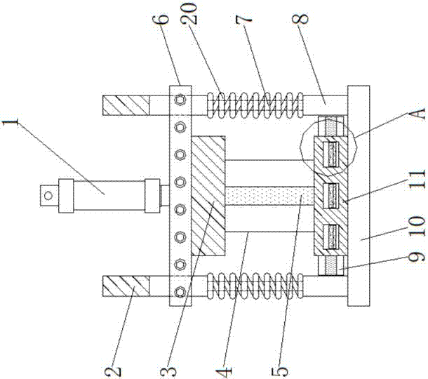
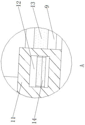
[0023] see Figure 1-7, the present invention provides a technical solution: a motor casing automatic stamping equipment, including a lower workbench 10, a lower mold 11 is fixedly connected above the lower workbench 10, and fixed rods 8 are connected to both sides of the lower mold 11, and the fixed rods 8 The top is fixedly connected with the connecting rod 7, and the connecting rod 7 is externally connected with a supporting spring 20, the supporting spring...


PUM


Abstract

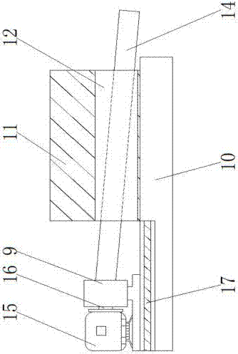
The invention relates to an automatic stamping device for a motor. The automatic stamping device comprises a lower working platform, wherein the upper part of the lower working platform is fixedly connected with a lower die; further, two sides of the lower die are connected with fixed rods; the upper parts of the fixed rods are fixedly connected with connecting rods; further, the exteriors of theconnecting rods are connected with supporting springs; the top ends of the connecting rods are movably connected with movable rods; further, the exteriors of the movable rods are connected with an upper working platform; the front of an upper die is connected with a supporting main frame; further, the interior of the supporting main frame is provided with a guide rail; the interior of the lower die is provided with die holes; further, the interiors of the die holes are movably connected with material receiving sheets; further, the interior of a material shaking platform is provided with a first slide way; the front of the material shaking platform is connected with a connecting shaft; further, the front of the connecting shaft is provided with a vibrating motor. The automatic stamping device for the motor can drive the material shaking platform to shake through the vibrating motor; thus, a waste material in the lower die is shaken off by the material receiving sheets driven by the material shaking platform when falling onto the material receiving sheets, and thus, the occurrence of a condition that the waste material is accumulated in the die holes is avoided.

Description

technical field [0001] The invention relates to the technical field of motor casing processing equipment, in particular to an automatic punching equipment for a motor casing. Background technique [0002] The electronic starter is the motor that people usually refer to now, also known as the starter; it drives the starter rotor to rotate through the energized coil in the magnetic field, and the small gear on the rotor drives the engine flywheel to rotate, thereby driving the crankshaft to rotate and start the car Two component innovations, new low-cost spark plugs and starters with ceramic core bases, laid the technological foundation for automotive development. [0003] The electronic starter abandoned the cumbersome and dangerous hand crank, making car driving safer, easier and more convenient, especially favored by a large number of new consumer groups including women; at that time, General Motors Cadillac branch manager Henry Leigh Lan immediately saw the potential of t...

Claims


Application Information

Patent Timeline
Patent Type & Authority Applications(China)
IPC IPC(8): B21D45/04
CPCB21D45/04
Inventor 曾信翰
Owner 东莞坤胜五金制品有限公司
Why Eureka
Eureka Blog
Learn More