
Single reactance compensation magnetic coupling resonance type wireless power transmission broadband E-type power amplifier

A resonant radio and power amplifier technology, which is applied in the field of electronics and radio frequency, can solve the problems of robustness and low resonant frequency, and achieve the effects of strong pertinence, loss reduction and simple structure

Inactive Publication Date: 2018-05-01
NANJING UNIV OF SCI & TECH
View PDF4 Cites 1 Cited by
  • Summary
  • Abstract
  • Description
  • Claims
  • Application Information

AI Technical Summary

Problems solved by technology

However, the power of wireless energy transmission is not large at present, staying at the level of 100 watts, which is far from meeting the needs of real life, and improving the transmission power mainly involves the following three issues: (1) the high-power broadband high-frequency power supply Design (2) Impedance matching of transmission system parameters (3) Power transmission stability issues, that is, resonance frequency robustness issues
In the actual process, due to the influence of factors such as the conduction voltage drop and parasitic resistance of the switching transistor, the efficiency of the E-class power amplifier is lower than 100%, but the actual efficiency of the circuit is still very high by modifying the parameters of the load circuit for optimization.

Method used


Image

  • Single reactance compensation magnetic coupling resonance type wireless power transmission broadband E-type power amplifier
  • Single reactance compensation magnetic coupling resonance type wireless power transmission broadband E-type power amplifier
  • Single reactance compensation magnetic coupling resonance type wireless power transmission broadband E-type power amplifier

Examples


Embodiment Construction

[0033] 1. Broadband class E power amplifier

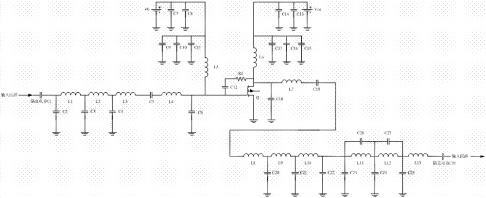
[0034] Broadband Class E power amplifiers have multiple different topological structures, the main difference being the type of reactance compensation circuit and matching circuit, what the present invention adopts is the wideband Class E power amplifier using single reactance compensation technology and Chebyshev low-pass impedance conversion circuit, Its circuit schematic diagram is as figure 2 shown.

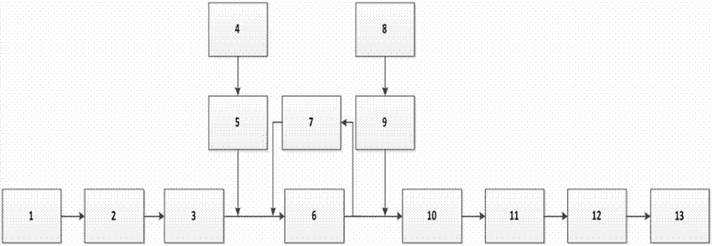
[0035] Input signal 1, input matching circuit 2 (composed of C2, C3, C4 and L1, L2, L3, L1, L2, L3 connected in series in the circuit, C2, C3, C4 connected in parallel to ground), input reactance compensation circuit 3 (composed of L4 , L5, C5, and C6, L4 and C5 are connected in series in the circuit, L5 is connected in series in the branch circuit of the gate bias power supply, C6 is connected to the ground), the gate bias power supply 4 is Vb, and the power filter circuit 5 (by C7 , C8, C9, C10, and C11 are connected in paral...


PUM


Abstract

The invention discloses a single reactance compensation magnetic coupling resonance type wireless power transmission broadband E-type power amplifier. The working process of the single reactance compensation magnetic coupling resonance type wireless power transmission broadband E-type power amplifier is as follows: an input signal (1) passes through an input matching circuit (2) and an input reactance compensation circuit (3); a gate bias power supply (4) is connected to the front end of a power tube (6) through a power supply filter circuit (5); a feedback circuit (7) is connected to two endsof the power tube (6) in parallel; a drain power supply (8) is connected to the rear end of the power tube (6) through a power supply filter circuit (9); and the output signal of the power tube (6) passes through an output reactance compensation circuit (10), an output matching circuit (11), and a low-pass elliptic filter circuit (12). Compared with the traditional single frequency point E-type power amplifier, ideal output power and efficiency can be kept on a relatively wide frequency band; the system output frequency is convenient to adjust; only the output signal frequency of a signal generation circuit needs to be adjusted; and furthermore, due to adoption of the low-pass elliptic filter circuit, the filter property of a broadband E-type power amplifier load network is improved.

Description

technical field [0001] Since the broadband type E power amplifier of the present invention is mainly applied to magnetic coupling resonance wireless power transmission, it mainly relates to the fields of electronics and radio frequency. Background technique [0002] Magnetically coupled resonant wireless power transfer technology is one of the three major technologies of wireless power transfer, and it is also one of the current research hotspots of scholars at home and abroad. However, the power of wireless energy transmission is not large at present, staying at the level of 100 watts, which is far from meeting the needs of real life, and improving the transmission power mainly involves the following three issues: (1) the high-power broadband high-frequency power supply Design (2) Impedance matching of transmission system parameters (3) Stability of power transmission, that is, the problem of robustness of resonance frequency. [0003] At present, there are mainly two ways...

Claims


Application Information

Patent Timeline
IPC IPC(8): H03F3/24
CPCH03F3/24
Inventor 张志仁李强王瑞霞赵雨清陆荣
Owner NANJING UNIV OF SCI & TECH
Learn More