a fixed mechanism

A fixing mechanism and first-line technology, applied in the direction of electrical components, etc., can solve the problems of different cable diameters, poor applicability of cable fixing fixtures, etc., to achieve good applicability, excellent shaping effect, and good fixing effect. Effect

Active Publication Date: 2020-05-29
无锡林亿机械制造有限公司
View PDF9 Cites 0 Cited by
  • Summary
  • Abstract
  • Description
  • Claims
  • Application Information

AI Technical Summary

Problems solved by technology

[0003] However, due to the different diameters of the cables, the applicability of the existing cable fixing clamps is not good in actual use, and it is difficult to meet the needs of the market

Method used


Image

  • a fixed mechanism
  • a fixed mechanism
  • a fixed mechanism

Examples


Embodiment 1

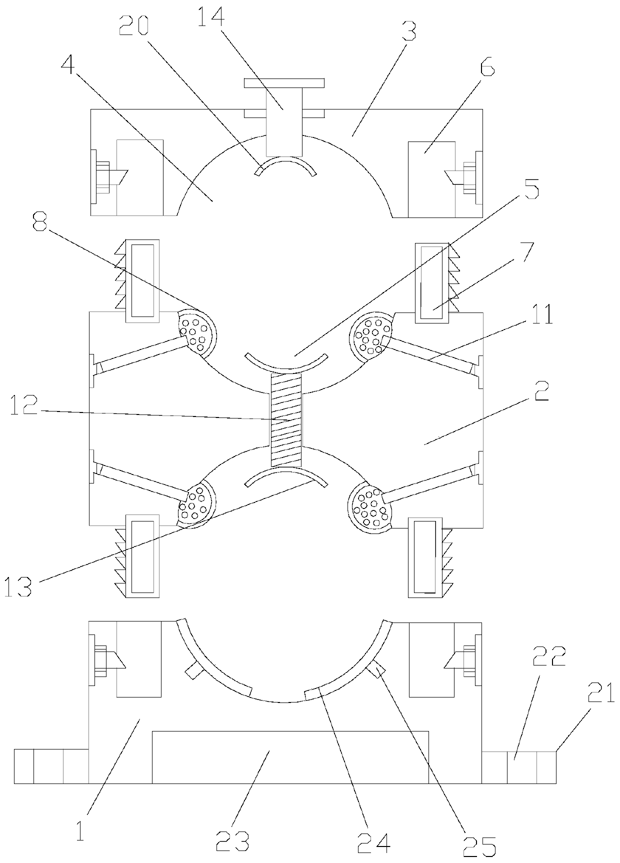
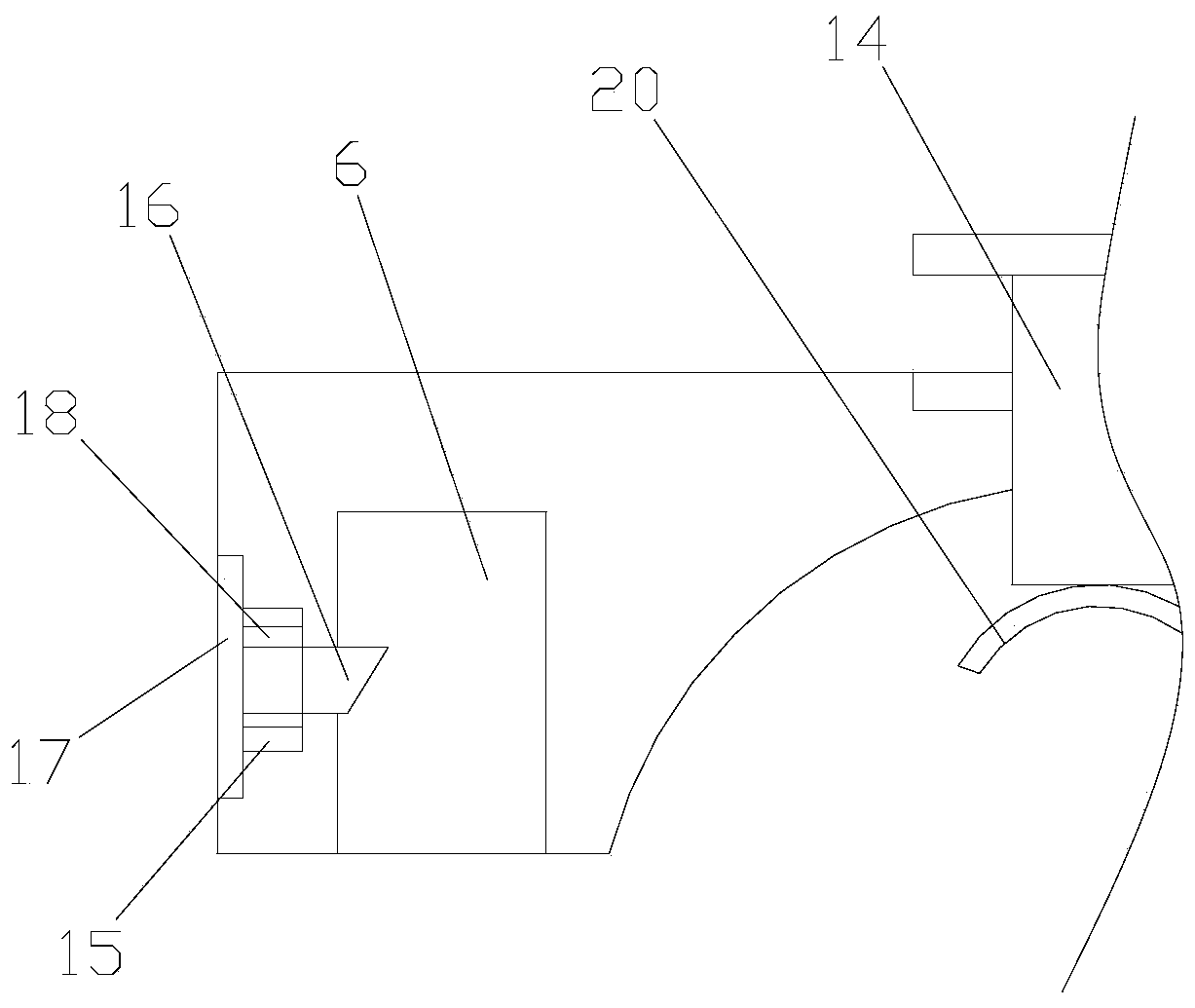
[0042] Such as Figure 1-3 As shown, a fixing mechanism includes a lower clamp 1, a middle clamp 2 and an upper clamp 3. The lower clamp 1 and the upper clamp 2 are each provided with a first wire slot 4, and the upper end surface and the lower clamp of the middle clamp 2 The end faces are all provided with a second wire groove 5 that is matched with the first wire groove 4, the lower clamp 1 and the upper clamp 3 are both provided with sockets 6, and the upper and lower end surfaces of the middle clamp 2 are both provided with The insertion rod 7 is matched with the insertion hole 6 and the insertion rod 7 is engaged with the insertion hole 6, an arc-shaped recess (not shown) is formed on the groove wall of the second wire groove 5, and the groove of the second wire groove 5 The wall is provided with a silicone sheet 8 for covering the depression. The silicone sheet 8 is glued to the groove wall of the second wire groove 5. A storage cavity 9 is formed between the silicone she...

Embodiment 2

[0050] Such as Figure 1-3 As shown, a fixing mechanism includes a lower clamp 1, a middle clamp 2 and an upper clamp 3. The lower clamp 1 and the upper clamp 2 are each provided with a first wire slot 4, and the upper end surface and the lower clamp of the middle clamp 2 The end faces are all provided with a second wire groove 5 that is matched with the first wire groove 4, the lower clamp 1 and the upper clamp 3 are both provided with sockets 6, and the upper and lower end surfaces of the middle clamp 2 are both provided with The insertion rod 7 is matched with the insertion hole 6 and the insertion rod 7 is engaged with the insertion hole 6, an arc-shaped recess (not shown) is formed on the groove wall of the second wire groove 5, and the groove of the second wire groove 5 The wall is provided with a silicone sheet 8 for covering the depression, the silicone sheet 8 is bonded to the groove wall of the second wire groove 5, and a storage cavity 9 is formed between the silicon...


PUM

PropertyMeasurementUnit
melting pointaaaaaaaaaa

Abstract

The invention discloses a fixing mechanism. The fixing mechanism comprises a lower fixture, a middle fixture and an upper fixture, wherein each of the lower fixture and the upper fixture is provided with a first cable tray, each of the upper end surface and the lower end surface of the middle fixture is provided with a second cable tray matched with the first cable tray, each of the lower fixtureand the upper fixture is provided with an insert hole, each of the upper end surface and the lower end surface of the middle fixture is provided with an insert rod matched with the insert hole, the insert rod and the insert hole are fitted, the wall of the second cable tray is provided with an arc concave, the wall of the second cable tray is provided with a silicon rubber sheet covering the concave, the silicon rubber sheet and the wall of the second cable tray are bonded, a storage cavity is formed between the silicon rubber sheet and the arc concave, the storage cavity is filled with liquidmetal, the middle fixture is provided with an insert hole, the insert hole is communicated with the storage cavity, an electric heating tube is inserted into the insert hole, and the tail of the electric heating tube is inserted into the storage cavity. The fixing mechanism has high applicability.

Description

Technical field [0001] The invention relates to the field of mechanical structures, in particular to a fixing mechanism. Background technique [0002] Most of the existing technology power distribution projects use high-drop shafts to lay and install power cables. Power cables used in power distribution projects generally have a large number of wires, a large section, and a heavier weight. Therefore, in order to ensure the stability of power cables, they generally need to be used. The clamp is used for fixing, and the cable fixing clamp is generally used to fix the cable. [0003] However, since the diameters of the cables are different, the existing cable fixing clamps are not well applicable in actual use, and it is difficult to meet the needs of the market. Summary of the invention [0004] The technical problem to be solved by the present invention is to provide a fixing mechanism with good applicability. [0005] To solve the above problems, the present invention adopts the fol...

Claims


Application Information

Patent Timeline
Patent Type & Authority Patents(China)
IPC IPC(8): H02G3/02C22C49/04C22C49/14C22C101/06
CPCC22C49/04C22C49/14H02G3/02
Inventor 严传玉
Owner 无锡林亿机械制造有限公司
Why Eureka
Try Eureka