
Chassis dynamometer and dynamometry unit thereof

A chassis dynamometer and dynamometer technology, which is applied in the direction of measuring devices, vehicle testing, machine/structural component testing, etc., and can solve problems such as easy concave deformation of the circulating transmission belt

Pending Publication Date: 2018-05-01
ZHENGZHOU DONGCHEN SCI & TECH
View PDF1 Cites 1 Cited by
  • Summary
  • Abstract
  • Description
  • Claims
  • Application Information

AI Technical Summary

Problems solved by technology

[0003] The purpose of the present invention is to provide a chassis dynamometer to solve the problem that the circulating transmission belt is easy to sink and deform in the prior art; the purpose of the present invention is also to provide a dynamometer unit used in the chassis dynamometer

Method used


Image

  • Chassis dynamometer and dynamometry unit thereof
  • Chassis dynamometer and dynamometry unit thereof
  • Chassis dynamometer and dynamometry unit thereof

Examples


Embodiment Construction

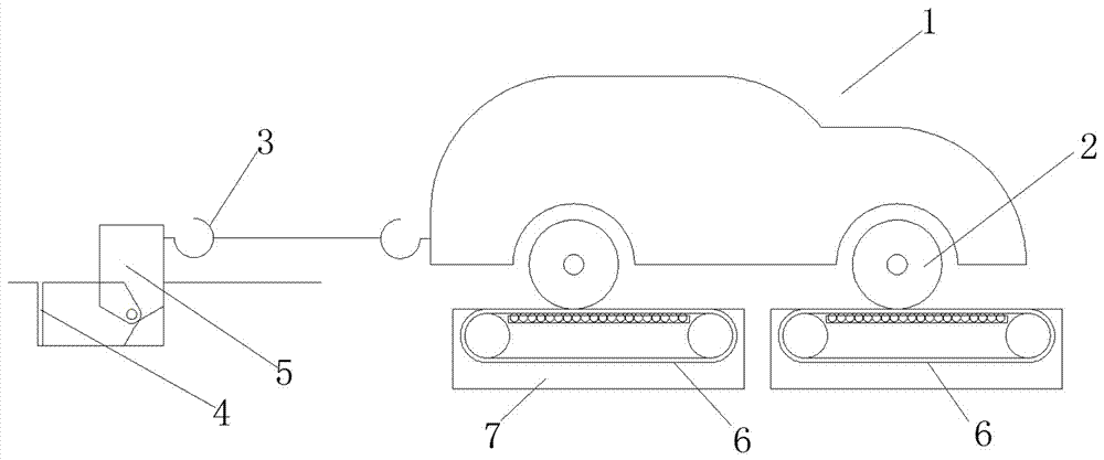
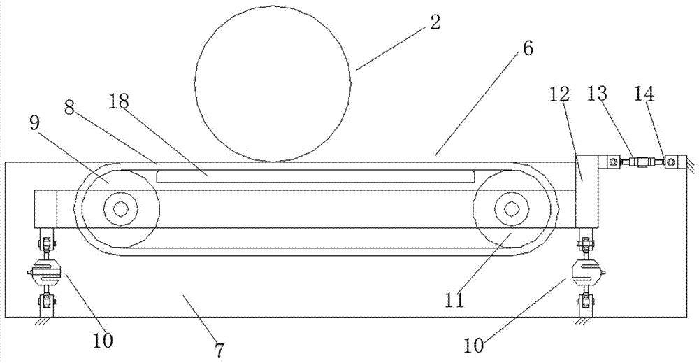
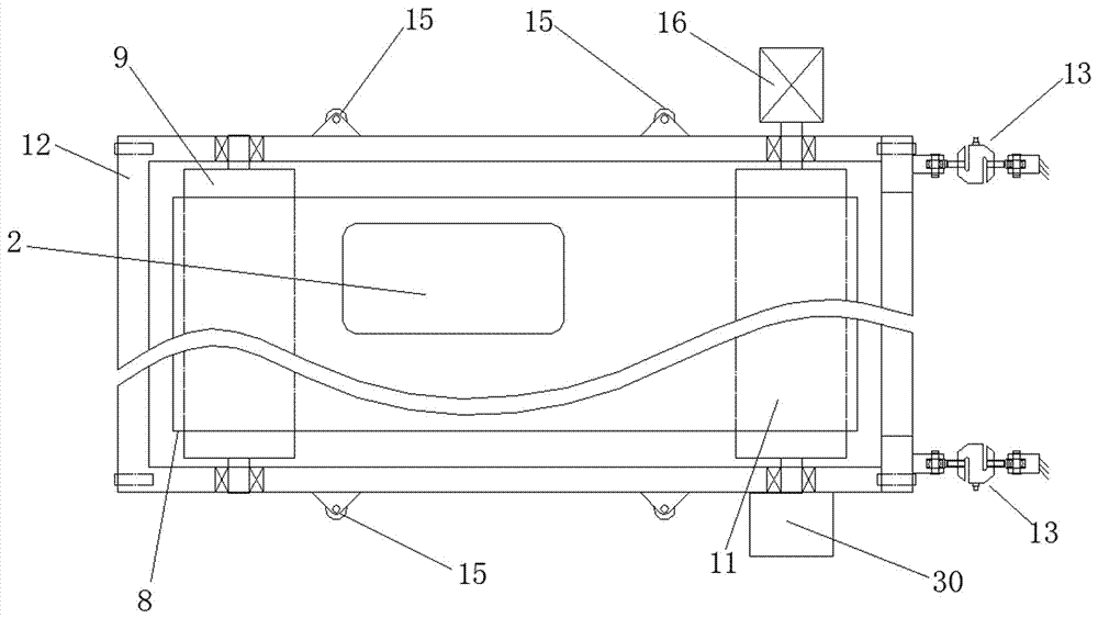
[0023] Examples of chassis dynamometers are Figure 1~5 As shown: it includes two pairs of dynamometer units arranged front and rear, and each pair of dynamometer units includes two dynamometer units 6 arranged left and right. The platform seat of the chassis dynamometer has accommodating grooves 7, and each dynamometer unit 6 is placed in the corresponding accommodating grooves 7, respectively. The chassis dynamometer also includes a fixing device used to prevent the position of the vehicle from changing during the test. The fixing device includes a hinged frame 5 hinged in the sinker on the rear side of the dynamometer unit. The hinged frame 5 is provided with a hook 3. During the test, The car can be fixed by arranging a stay rope between the hinged frame and the car to prevent the car from moving forward, and the hinged frame is not in use. Can be turned over into sinker 4.

[0024] The structure of each dynamometer unit is the same, and now only one of the dynamometer u...


PUM


Abstract

The invention relates to a chassis dynamometer and a dynamometry unit thereof. The chassis dynamometer comprises a carrying support, wherein a driven wheel and a driving wheel driven by a driving mechanism are arranged on the carrying support; the driving wheel is connected with the dynamometer; a circulating transmission belt which is in corresponding friction and rolling fit with a vehicle is wound on the driving wheel and the driven wheel; a supporting body which is fixed relative to the carrying support is arranged on the lower side of a circulating supporting belt portion on the upper side; the circulating supporting belt has the two arrangement modes, in the first mode, the circulating supporting belt is a flexible belt, a supporting body is a supporting flat plate which is in supporting fit with the circulating supporting belt portion on the upper side, in the second mode, the circulating supporting belt is a rigid belt and comprises a plurality of rigid belt sections which areconnected end to end successively in a hinged manner, and the supporting body is a supporting flat plate matched with the circulating supporting belt on the upper side or at least two supporting strips which are arranged at intervals in the left-right direction. The invention provides the chassis dynamometer capable of simulating a real vehicle running environment and the dynamometry unit used inthe chassis dynamometer.

Description

technical field [0001] The invention relates to a chassis dynamometer and a dynamometer unit thereof in the field of automobile testing. Background technique [0002] Chassis dynamometer is the key testing equipment for vehicle dynamic performance testing, and chassis dynamometer can be used to test vehicle dynamic performance. Existing chassis dynamometers such as "a belt transmission device for chassis dynamometer" disclosed in Chinese patent CN203051647U, the belt transmission device includes a driving wheel and a driven wheel arranged front and rear, and the driving wheel and the driven wheel are wound on the useful The wedge-shaped belt that is frictionally and rollingly matched with the corresponding wheel is the endless transmission belt. During the test, the test is realized by the wedge-shaped belt and the wheel transmission. The existing belt transmission device has the following problems. The use of the transmission belt structure itself is to more realistically ...

Claims


Application Information

Patent Timeline
IPC IPC(8): G01M17/007
CPCG01M17/007
Inventor 尚廷东马浩翔尚晓玉朱蕾蕾刘辉毛志丹柯存荣孙亮冯云
Owner ZHENGZHOU DONGCHEN SCI & TECH
Learn More