Power-driven return material clearing scraper conveying device

A power-driven, conveying device technology, applied in the field of machinery, can solve problems such as heavy return materials, motor burnout, and production delays, and achieve the effects of low manufacturing cost, reliable power, and simple structure

Pending Publication Date: 2020-01-14
刘素华
View PDF6 Cites 0 Cited by
  • Summary
  • Abstract
  • Description
  • Claims
  • Application Information

AI Technical Summary

Problems solved by technology

[0002] The conveyor belt of the old belt feeder and the armor belt feeder is fed by the driving roller and the driven roller by friction. There are gaps in the perforation, there are gaps between multiple nails, etc., which are affected by tension, temperature, and the deflection of the rollers and rollers, etc., which will inevitably lead to the frequent deviation of the belt and nail belt during operation, resulting in material leakage and return. The material is serious and the leakage is serious. In order to solve the problems of material leakage and return material, a return material collector is added to the lower part of the feeder chassis. The old return material collector is driven by a separate power, with a complex structure and large volume and weight. Occupies a lot of space on the site, resulting in high investment costs for site infrastructure and equipment. Due to the separate power setting, the return material collector is only started after a large amount of return coal has accumulated on the site. If it is damaged, the motor will burn out and cannot work, delaying production, and causing a lot of waste of maintenance materials. With the improvement of the conveying function and energy saving of conveying equipment in society, in order to solve the above problems, through decades of research and development, manufacturing and further research, the present invention proposes A scraper conveying device driven by power to clean and return materials

Method used


Image

  • Power-driven return material clearing scraper conveying device
  • Power-driven return material clearing scraper conveying device
  • Power-driven return material clearing scraper conveying device

Examples


Embodiment 1

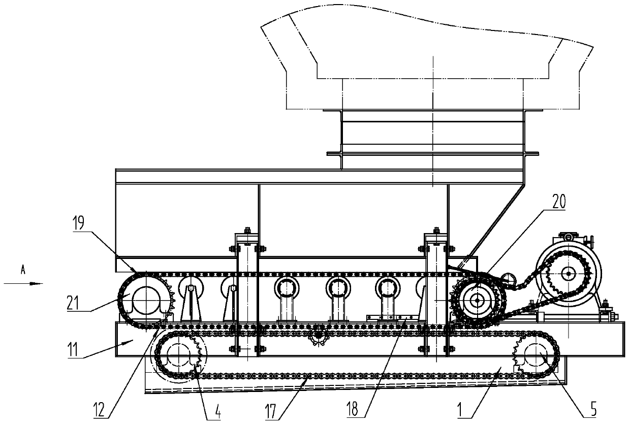
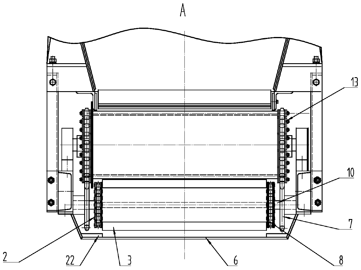
[0031] Such as Figure 1 to Figure 2 As shown, the scraper conveying device 1 driven by power to clean the returning material includes a scraper chain 2 for clearing the returning material, a scraper for clearing the returning material 3, a driving gear for clearing 4, a gear for redirecting the clearing 5 and a lower cleaning hopper 6, The cleaning driving gear part 4 includes the cleaning transmission gear 7, the hanging cleaning chain driving gear 8, the cleaning driven gear 9 and the cleaning gear shaft 10, and the cleaning gear shaft 10 is connected with the fixed cleaning transmission gear 7 and the cleaning chain. The material chain drive gear 8 is used to drive the cleaning scraper conveying device for the return journey by power. 1 includes borrowed power mechanism 12, which includes buckle side positioning bar ring chain 13, side positioning bar teeth 14, drum side end drive sprocket 15 or drum side end drive gear 16, cleaning transmission gear 7 and buckle The ring...

Embodiment 2

[0036] Such as image 3 As shown, the material cleaning transmission gear 7 is fastened with the side positioning bar teeth 14, and the side positioning bar teeth 14 rotate to drive the cleaning material transmission gear 7 to rotate.

[0037] Others are with embodiment 1.

Embodiment 3

[0039] Such as Figure 4 to Figure 5 As shown, the cleaning transmission gear 7 is fastened with the drum side drive sprocket 15, and the rotation of the drum side drive sprocket 15 drives the cleaning transmission gear 7 to rotate.

[0040] Others are with embodiment 1.


PUM


Abstract

The invention belongs to the field of machinery, and particularly relates to a power-driven return material clearing scraper conveying device. According to the conveying device, material clearing gearshafts are connected and fixed to material clearing transmission gears and hanging material clearing chain driving gears in a penetrating manner and are supported by machine frames or supported by lower material clearing hoppers, the material clearing transmission gears drive the hanging material clearing chain driving gears to rotate, return material clearing scrapers are arranged between two return material clearing scraper chains, and the return material clearing scraper chains are buckled on the hanging material clearing chain driving gears and material clearing reversing gear parts in asurrounding manner to form return material clearing scraper conveyors. The conveying device has the advantages that the material clearing transmission gears drive the hanging material clearing chain driving gears to rotate, so that the power for clearing return materials is saved, the active power on buckle tooth multi-dimensional integral leakage-proof side positioning bands is used as the powerfor clearing return coal, and therefore the power for clearing the return materials is increased, it is guaranteed that the power of the power-driven return material clearing scraper conveying deviceis reliable, the structure is simple, and the return material clearing effect is good.

Description

technical field [0001] The invention belongs to the field of machinery, and in particular relates to a scraper conveying device driven by power for cleaning return materials. Background technique [0002] The conveyor belt of the old belt feeder and the armor belt feeder is fed by the driving roller and the driven roller by friction. There are gaps in the perforation, there are gaps between multiple nails, etc., which are affected by tension, temperature, and the deflection of the rollers and rollers, etc., which will inevitably lead to the frequent deviation of the belt and nail belt during operation, resulting in material leakage and return. The material is serious and the leakage is serious. In order to solve the problems of material leakage and return material, a return material collector is added to the lower part of the feeder chassis. The old return material collector is driven by a separate power, with a complex structure and large volume and weight. Occupies a lot ...

Claims


Application Information

Patent Timeline
Patent Type & Authority Applications(China)
IPC IPC(8): B65G19/18B65G23/06B65G21/22B65G19/20
CPCB65G19/18B65G23/06B65G21/22B65G19/20Y02P70/10
Inventor 刘素华闫玉岗张玉善汤海峰常孟
Owner 刘素华
Why Eureka
Try Eureka