Formation water discharge equipment for oil exploitation
A technology for formation water and petroleum, which is applied in the fields of fluid extraction, earthwork drilling, filtration and separation, etc. It can solve problems such as clogging of filter screens, clogging of seepage tanks, and affecting the normal operation of drainage devices, so as to improve convenience and efficiency Effect
- Summary
- Abstract
- Description
- Claims
- Application Information
AI Technical Summary
Problems solved by technology
Method used
Image
Examples
Embodiment 1
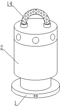
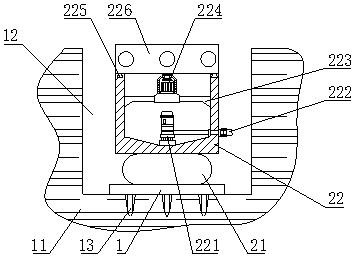
[0034] Such as Figure 1-8As shown, the present invention provides a formation water discharge device for petroleum exploitation, comprising a fixed base 1 and a mine floor 11, a drainage groove 12 is opened on the top of the mine floor 11, and the fixed base 1 is movably connected to the inner cavity of the drainage groove 12 The bottom of the fixed base 1 is fixedly welded with a stabilizing plunger 13, and the stabilizing plunger 13 is movably connected to the inside of the mine ground 11. The top of the fixed base 1 is provided with a filter discharge mechanism 2. On the outer wall of the fixed base 1 An anti-blocking mechanism 3 is provided, and the filter discharge mechanism 2 includes a lifting mechanism 21 and a drainage box body 22. A support frame 223 is fixedly installed on the inner wall of the drainage box body 22, and a rotation control motor 224 is fixedly installed on the top of the support frame 223, and the support frame The top of 223 is fixedly installed wi...
Embodiment 2
[0036] Such as Figure 1-8 As shown, on the basis of Embodiment 1, the present invention provides a technical solution: preferably, the inner wall of the hollow frame 226 is fixedly welded with a central driving bracket 227, and the output shaft of the rotation control motor 224 is connected to the bottom of the central driving bracket 227 Fixedly connected, the bottom of the inner cavity of the drainage box 22 is fixedly equipped with a submersible pump body 221, and the outlet pipe of the submersible pump body 221 extends to the right side of the drainage box 22 and is threaded to extend the output pipe 222, and the inner wall of the filter cartridge 228 is fixed. Welded with an internal thread ring 2281, the inner cavity of the internal thread ring 2281 is threaded with a fine filter screen cover 2282, the back of the filter cartridge 228 is provided with a cylindrical groove, and an elastic connecting rope 2283 is arranged in the inner cavity of the cylindrical groove, and ...
Embodiment 3
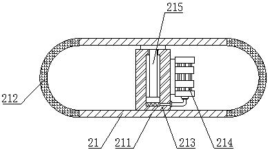
[0038] Such as Figure 1-8 As shown, on the basis of Embodiment 1, the present invention provides a technical solution: preferably, the lifting mechanism 21 includes a connecting base plate 211, and there are two connecting base plates 211, one of which is fixedly welded on the fixed base 1 The other connecting base plate 211 is fixedly welded on the bottom of the drainage box 22, and an elastic rubber cover 212 is fixedly connected between the two connecting base plates 211, and a fixed cylinder 213 is fixedly installed on the top of the connecting base plate 211 located below. The right side of 213 is fixedly installed with micro air pump 214, and the output pipe of micro air pump 214 is fixedly connected with the right side of fixed cylinder 213, and the inner chamber of fixed cylinder 213 is slidably connected with sliding lifting rod 215, and the top of sliding lifting rod 215 is positioned at The bottom of the upper connecting base plate 211 is fixedly connected, and the...
PUM
 Abstract
Description
Claims
Application Information
 - R&D
- Intellectual Property
- Life Sciences
- Materials
- Tech Scout
- Unparalleled Data Quality
- Higher Quality Content
- 60% Fewer Hallucinations
Browse by: Latest US Patents, China's latest patents, Technical Efficacy Thesaurus, Application Domain, Technology Topic, Popular Technical Reports.
© 2025 PatSnap. All rights reserved.Legal|Privacy policy|Modern Slavery Act Transparency Statement|Sitemap|About US| Contact US: help@patsnap.com


