Injection tube cutting device

A technology for cutting devices and injection-molded pipes, applied in metal processing, etc., which can solve the problems of time-consuming and laborious, high requirements for workers and equipment, and inability to process injection-molded pipes of different specifications

Active Publication Date: 2019-03-26
宁波高新区新柯保汽车科技有限公司
View PDF5 Cites 0 Cited by
  • Summary
  • Abstract
  • Description
  • Claims
  • Application Information

AI Technical Summary

Problems solved by technology

[0003] The above method has the following defects: 1. The turning tool must be accurately controlled to ensure that the turning tool moves evenly, and the movement of the turning tool must be well coordinated with the rotation of the injection molding tube
2. It is time-consuming and labor-intensive to install and disassemble the injection molding pipe for each processing, and for injection molding pipes of different diameters, the fixture must be replaced
3. The adjustment of the processing groove depth in the prior art relies entirely on manual operation, which has high requirements for workers and equipment, and the processing of injection molded pipes with different diameters requires frequent adjustment of tools
[0004] In summary, the existing injection molding pipe cutting device cannot directly process injection molding pipes of different specifications

Method used


Image

  • Injection tube cutting device
  • Injection tube cutting device
  • Injection tube cutting device

Examples


Embodiment Construction

[0028] The following is further described in detail through specific implementation methods:

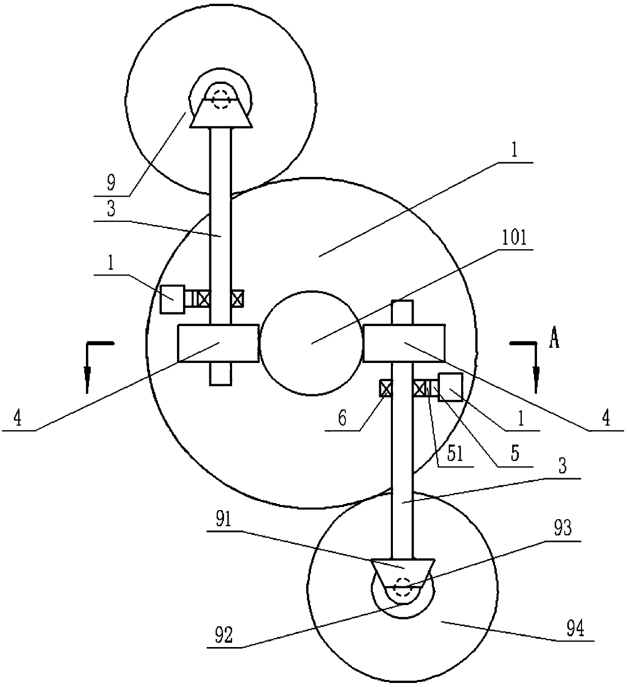
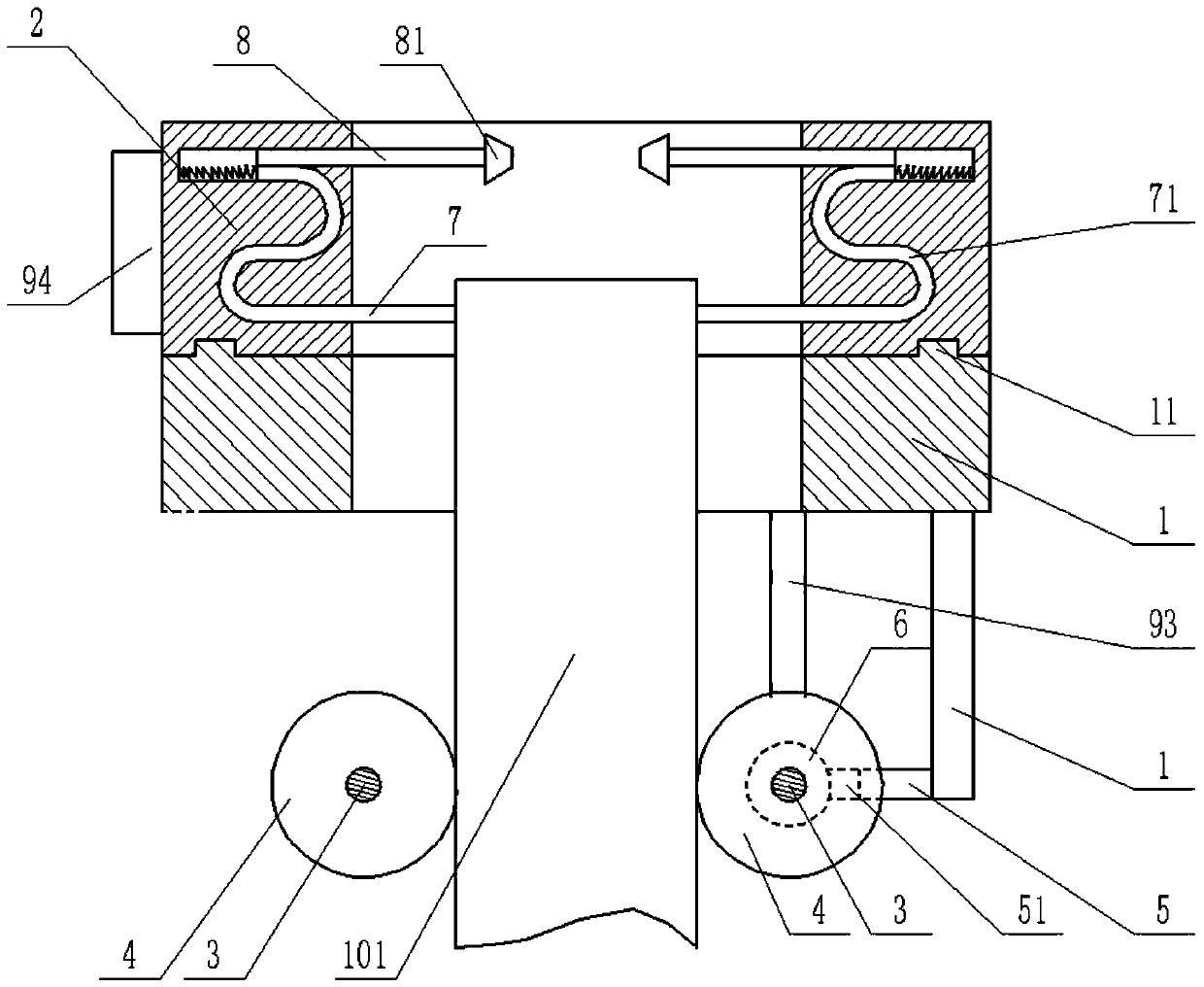
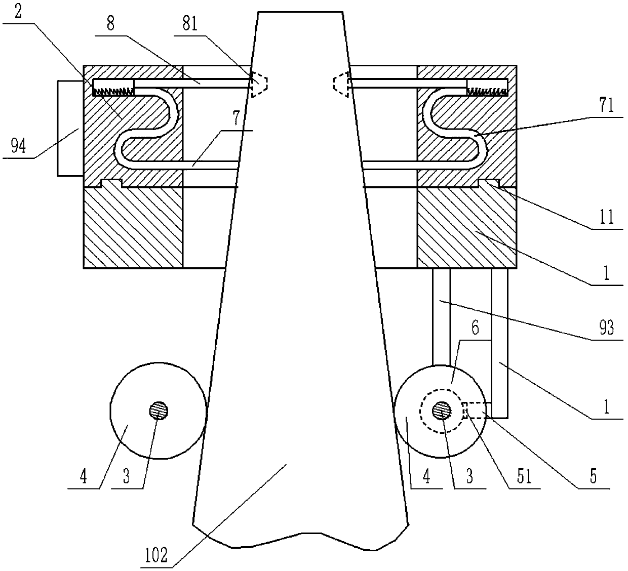
[0029] The reference signs in the drawings of the description include: processing table 1, protrusion 11, first external gear 2, rotating shaft 3, friction wheel 4, telescopic rod 5, telescopic end 51, bearing 6, hard tube 7, S-shaped channel 71. Knife rest 8, cutter 81, transmission unit 9, first bevel gear 91, second bevel gear 92, transmission shaft 93, second external gear 94, injection molding tube 101, tapered injection molding tube 102.

[0030] The embodiment is basically as attached figure 1 , figure 2 As shown: the injection molding pipe cutting device includes a cylindrical processing table 1 and a first external gear 2, the processing table 1 is vertically arranged, the first external gear 2 is coaxially connected to the upper end surface of the processing table 1, and the first The lower end surface of the external gear 2 is provided with an annular groove along the c...


PUM


Abstract

The invention relates to the technical field of machining of injection molding parts, in particular to an injection molding pipe cutting device. The injection molding pipe cutting device comprises a tubular machining table and a first outer gear, wherein the machining table is vertically arranged, the first outer gear is coaxially and rotationally connected to the upper end face of the machining table, two rotary shafts horizontally arranged in parallel are arranged below the machining table and rotationally connected with the machining table, the two rotary shafts are located on the two sidesof a vertical center axis of the machining table and fixedly connected with friction wheels which are symmetrical with respect to the vertical center axis of the machining table, an S-shaped pore duct is arranged in the first outer gear, and a hard pipe is arranged in the S-shaped pore duct in a sliding fit mode. The injection molding pipe cutting device can machine injection molding pipes of different specifications directly.

Description

technical field [0001] The invention relates to the technical field of injection molding parts processing, in particular to an injection molding pipe cutting device. Background technique [0002] The injection molding tube is made by mixing resin powder, stabilizer and other materials, and then crushing to obtain rubber particles, which are finally added to the extrusion injection molding machine. Injection molding pipes have many different diameter specifications, and thread-like grooves need to be processed on the outer surfaces of injection molding pipes of different diameters during production. The method adopted in the prior art is to use a fixture to fix the injection tube on the chuck of the lathe, start the main shaft of the lathe, and the chuck drives the injection tube to rotate. Every time the injection tube rotates with the chuck, the turning tool is evenly moved along the axial direction of the injection tube. Move a lead. [0003] The above method has the fol...

Claims


Application Information

Patent Timeline
Patent Type & Authority Patents(China)
IPC IPC(8): B26D3/06B26D3/11B26D5/38B26D7/02B26D7/06B26D7/26
CPCB26D3/06B26D3/11B26D5/38B26D7/02B26D7/0608B26D7/2614B26D7/2628B26D2007/013
Inventor 项文增
Owner 宁波高新区新柯保汽车科技有限公司
Why Eureka
Try Eureka