
A pipe fitting clamping device for automatic machinery

A technology for clamping devices and pipe fittings, applied in the directions of clamping devices, metal processing machinery parts, positioning devices, etc., can solve problems such as poor clamping effect, and achieve the effect of preventing direct extrusion and increasing the clamping degree.

Active Publication Date: 2019-11-19
安徽新立滤清器有限公司
View PDF5 Cites 0 Cited by
  • Summary
  • Abstract
  • Description
  • Claims
  • Application Information

AI Technical Summary

Problems solved by technology

[0004] The purpose of the present invention is to provide a pipe fitting clamping device for automatic machinery, which has the advantage of good clamping effect and solves the problem of poor clamping effect of common pipe fitting clamping devices

Method used


Image

  • A pipe fitting clamping device for automatic machinery
  • A pipe fitting clamping device for automatic machinery
  • A pipe fitting clamping device for automatic machinery

Examples


Embodiment Construction

[0018] The following will clearly and completely describe the technical solutions in the embodiments of the present invention with reference to the accompanying drawings in the embodiments of the present invention. Obviously, the described embodiments are only some, not all, embodiments of the present invention. Based on the embodiments of the present invention, all other embodiments obtained by persons of ordinary skill in the art without making creative efforts belong to the protection scope of the present invention.

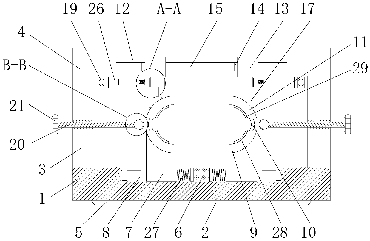
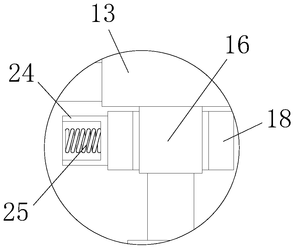
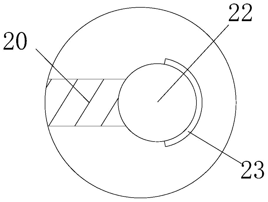
[0019] see Figure 1-3 , a pipe fitting clamping device for automated machinery, comprising a base plate 1, a slide rail 2 is provided at the bottom of the base plate 1, the slide rail 2 is used to be installed on an automated machine, and support plates 3 are fixedly connected to both sides of the top of the base plate 1, The tops of the two support plates 3 are fixedly connected by the top plate 4, the top of the bottom plate 1 is provided with a first chute...


PUM


Abstract

The invention discloses a pipe fitting clamping device for an automatic machine. The pipe fitting clamping device comprises a bottom plate, a sliding rail is arranged at the bottom of the bottom plate, and supporting plates are fixedly connected to the two sides of the top of the bottom plate; and the tops of the two supporting plates are fixedly connected through a top plate, a first sliding groove is formed in the top of the bottom plate, and a fixing block is fixedly connected to the middle point of the bottom of the inner wall of the first sliding groove. According to the pipe fitting clamping device for the automatic machine, a second sliding groove, second sliding blocks, pneumatic telescopic rods, abutting blocks, annular sleeves and second air cylinders are arranged, and the problem that the clamping effect of a common pipe fitting clamping device is not good is solved, so that the stress at each part of the pipe fitting can be reasonably distributed; and when the pipe fittingis machined, shaking of the pipe fitting caused by unstable fixing due to the fact that the tensioning force in one part of the fitting is too large or too small does not occur, so that the expected machining purpose is achieved accurately, the clamping radius is conveniently adjusted according to the diameter of a pipe, and great convenience is brought to a user.

Description

technical field [0001] The invention relates to the technical field of automatic machinery, in particular to a pipe fitting clamping device for automatic machinery. Background technique [0002] Any automated machinery is composed of three parts: actuators, sensors, and controllers. Automated machinery is widely used in industry, agriculture, military, scientific research, transportation, commerce, medical care, services, and households. Technology can not only liberate people from heavy physical labor, some mental work, and harsh and dangerous working environments, but also expand human organ functions and greatly improve labor productivity. For some automated machinery that needs to clamp pipes , such as automatic grinding machines, automatic cutting machines, etc., often need to fix the pipes to be processed, so how to make the clamping effect of pipe fittings better is a problem that must be solved at present. [0003] The clamping effect of common clamping devices for ...

Claims


Application Information

Patent Timeline
Patent Type & Authority Patents(China)
IPC IPC(8): B23Q3/08B24B41/06B23Q11/00
CPCB23Q3/064B23Q3/08B23Q11/0032B23Q2703/04B24B41/067
Inventor 何伯春
Owner 安徽新立滤清器有限公司
Learn More