Solid-sealed pole and dual power switch

A technology of solid-sealed poles and poles, which is applied in the direction of electric switches, high-voltage/high-current switches, circuits, etc., can solve the problems of inconvenient installation and large volume, reduce mechanism settings, control the overall volume, and reduce the number of settings Effect

Active Publication Date: 2021-01-05
天津市先智电气设备有限公司
View PDF7 Cites 0 Cited by
  • Summary
  • Abstract
  • Description
  • Claims
  • Application Information

AI Technical Summary

Problems solved by technology

[0002] The medium-voltage dual power supply transfer switch uses solid-sealed poles. Each pole of each power supply phase uses one pole, and then the outlet terminals of the two power supplies are connected in parallel. For a three-phase dual power supply, this requires six poles, 12 terminals, the wiring structure is responsible, and because of the insulation distance, the volume is large and the installation is inconvenient

Method used


Image

  • Solid-sealed pole and dual power switch
  • Solid-sealed pole and dual power switch
  • Solid-sealed pole and dual power switch

Examples


no. 1 Embodiment

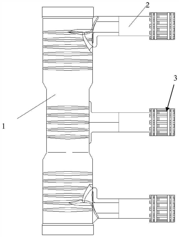
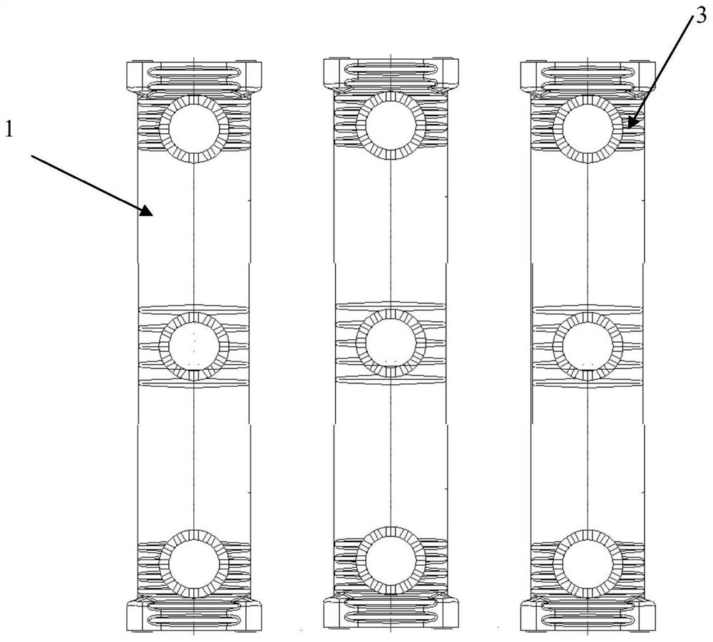
[0024] As shown in the figure, the solid-sealed pole of this embodiment includes a pole body 1, and three side-extruded contact arms 2 are formed at intervals at both ends of the same side or different sides of the pole body and in the middle. Connecting terminals 3 are formed on each part, such as duckbill contacts, plum blossom village contacts, etc., and vacuum bubbles are respectively arranged in the pole bodies between two adjacent contact arms. That is, one solid-sealed pole contains two vacuum bubbles, and the pole body, the contact arm and the two vacuum bubbles are integrally cast. Action mechanisms matching the vacuum bubbles are respectively provided at both ends of the pole body, which are similar to the prior art. Preferably, in order to balance the insulation effect and volume, a creepage wall is provided at the connection between the contact arm and the pole body, wherein the vacuum bubbles are arranged axially along the pole body. Of course, in order to improv...

no. 2 Embodiment

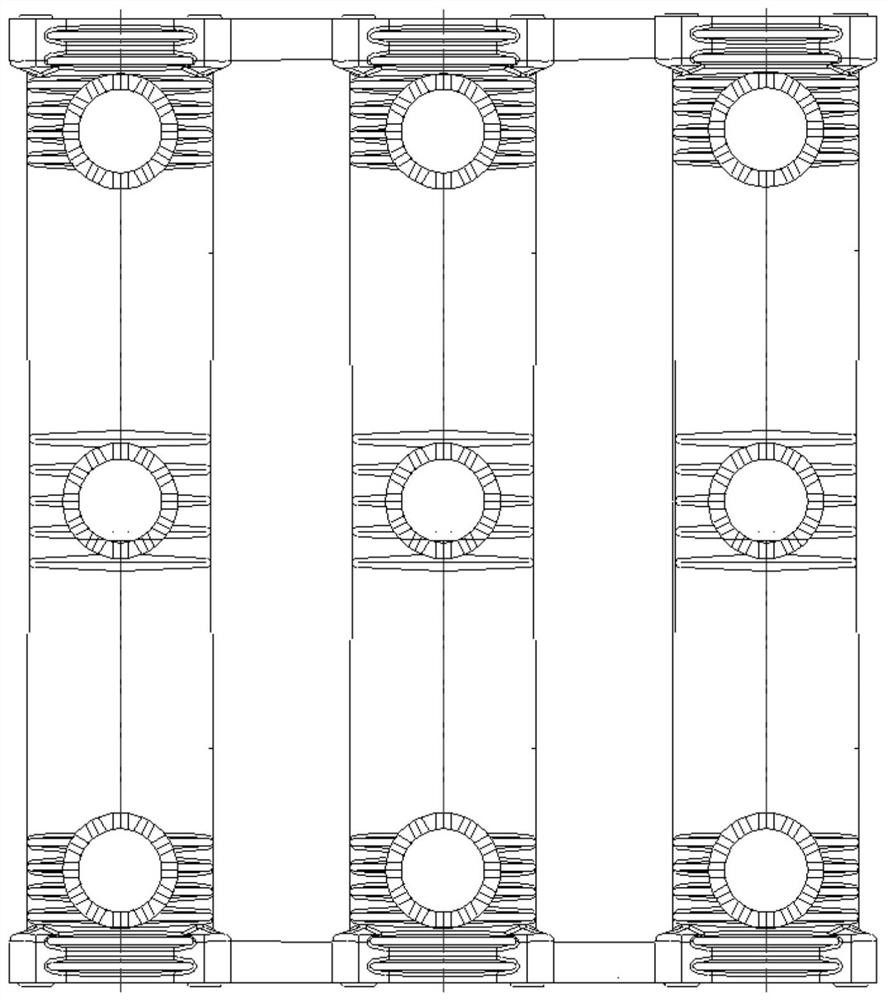
[0030] As shown in the figure, the solid-sealed pole set of this embodiment includes two terminal input pole groups 10 and three intermediate output contact arms 20. The integral column body 100 is one-to-one correspondingly formed on the terminal contact arm 101 on one side of the column body, one-to-one correspondingly formed on the terminal 102 at the end of the column body, such as a copper bar, and correspondingly arranged on the terminal contact arm and The vacuum bubble in the column body between the terminals, the vacuum bubble includes a vacuum bubble body and two terminals arranged therein, the terminals are respectively electrically connected to the terminal contact arm and the terminal, and the intermediate output contact The arm is arranged between the end input pole groups arranged adjacent to the two terminals, and the middle output contact arms are respectively electrically connected to the corresponding terminals of the two end input pole groups, and the ends o...


PUM


Abstract

The invention discloses an enclosed pole post. The enclosed pole post comprises two end input pole posts and an intermediate output contact arms, wherein each end input pole post comprises a post body, an end contact arm, wiring terminals and a vacuum tube, wherein the end contact arm is formed at one side of the post body, the wiring terminals are correspondingly formed at an end part of the postbody, the vacuum tube is correspondingly arranged in the post body between the end contact arm and the wiring terminals, and the intermediate output arm is arranged between the two end input post posts and is electrically connected with the corresponding wiring terminals. In the enclosed pole post, the pole post correspondingly to each phase power is of an E-shaped structure, the two traditionalpost posts are respectively output, then are connected in parallel and are output from a middle part after integrating by direct casting, the arrangement number of an output end is reduced, parallel connection after the pole post is output is prevented, the arrangement of the mechanism is reduced, and the whole volume is effectively controlled.

Description

technical field [0001] The invention relates to the technical field of electrical switches, in particular to a solid-sealed pole and a dual-power switch. Background technique [0002] The medium-voltage dual power supply transfer switch uses solid-sealed poles. Each pole of each power supply phase uses one pole, and then the outlet terminals of the two power supplies are connected in parallel. For the three-phase dual power supply, this requires six poles, 12 terminals, the wiring structure is responsible, and because of the insulation distance, the volume is large and the installation is inconvenient. Contents of the invention [0003] The object of the present invention is to provide a solid-sealed pole and a dual-power switch for the technical defects in the prior art. [0004] The technical scheme adopted for realizing the purpose of the present invention is: [0005] A solid-sealed pole, comprising a pole body, three side-extruded contact arms are formed at both end...

Claims


Application Information

Patent Timeline
Patent Type & Authority Patents(China)
IPC IPC(8): H01H33/66H01H33/662
CPCH01H33/6606H01H33/66207H01H2033/66223
Inventor 王平王金杰
Owner 天津市先智电气设备有限公司
Why Eureka
Try Eureka