
Feeding device for injection mold

A feeding device and injection mold technology, applied in the field of chemical equipment, can solve the problems of dehumidification and dust removal of plastic raw materials, mixing of large dust and impurities, and affecting the quality of molded plastics, etc., to achieve scientific and reasonable overall equipment, low energy consumption, and huge economic benefits Effect

Inactive Publication Date: 2018-04-27
DONGGUAN ZHIPEI ELECTROMECHANICAL TECH CO LTD
View PDF0 Cites 3 Cited by
  • Summary
  • Abstract
  • Description
  • Claims
  • Application Information

AI Technical Summary

Problems solved by technology

[0003] At present, the injection mold feeding devices on the market directly push the plastic raw materials into the barrel of the injection molding machine under high pressure, without dehumidification and dust removal for the plastic raw materials, because a large amount of dust and impurities will be mixed in the plastic raw materials during the production, processing, transportation and mixing process , if it is not treated, it will seriously affect the quality of the molded plastic, and because many plastic raw materials have strong hygroscopicity, the water content must be reduced before the product is formed to avoid air bubbles in the subsequent hot-melt injection molding process that will affect the quality and service life of the product. , Aiming at the above problems, a feeding device for injection molds is proposed

Method used


Image

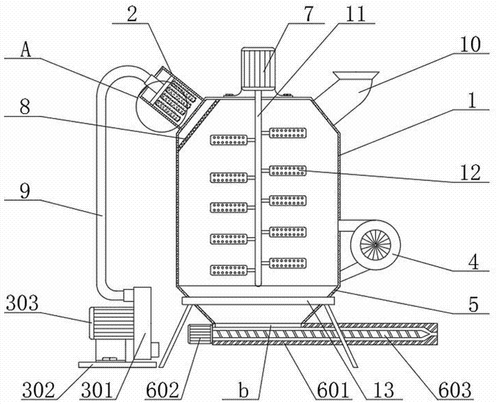
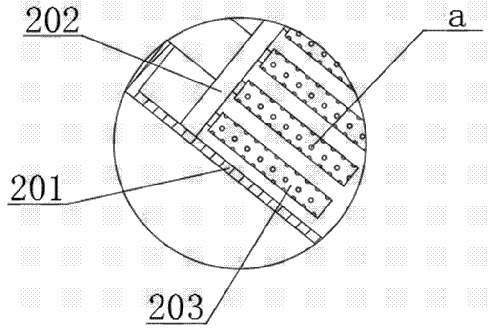
  • Feeding device for injection mold
  • Feeding device for injection mold

Examples


Embodiment Construction

[0018] The following will clearly and completely describe the technical solutions in the embodiments of the present invention with reference to the accompanying drawings in the embodiments of the present invention. Obviously, the described embodiments are only some, not all, embodiments of the present invention. Based on the embodiments of the present invention, all other embodiments obtained by persons of ordinary skill in the art without making creative efforts belong to the protection scope of the present invention.

[0019] see Figure 1-2 , the present invention provides a technical solution:

[0020] A feeding device for an injection mold, comprising a stirring box 1, a dust collection device 2, a high-pressure fan assembly 3, a propulsion device 6 and a support frame 13, the upper right end of the stirring box 1 is fixedly connected with a feeding hopper 10, and the stirring box 1. The second motor 7 is fixedly connected to the center of the top, and the end of the mai...


PUM


Abstract

The invention relates to the technical field of chemical equipment, in particular to a feeding device for an injection mold. The feeding device for the injection mold comprises a stirring box, a dustsucking device, a high pressure fan assembly, a propelling device and a supporting frame. The center of the top end of the stirring box is fixedly connected with a second motor. The tail end of a mainshaft of the second motor is fixedly connected with a vertically arranged stirring rod. The right side of the stirring box is fixedly connected with an air heater which can dry and dehumidify plasticraw materials. The dust sucking device is arranged at the left upper end of the stirring box, comprises a dust removal box, an air guide pipe and a dust removal filter core, and can conduct dust removal on the plastic raw materials. The propelling device comprises a propelling pipe, a first motor and a propelling screw rod. A feeding inlet is formed in the top end of the left side of the propelling pipe. The bottom end of the stirring box is fixedly connected with a collection hopper. The bottom end of the collection hopper is fixedly connected with the propelling pipe. The feeding device forthe injection mold is scientific and reasonable in structure, has great economic benefits and wide market demand, and is worth popularizing.

Description

technical field [0001] The invention relates to the technical field of chemical equipment, in particular to a feeding device for an injection mold. Background technique [0002] Injection molding is a tool for producing plastic products; it is also a tool for giving plastic products a complete structure and precise dimensions. Injection molding is a processing method used in mass production of certain complex-shaped parts. The injection molding machine is injected into the mold cavity under high pressure, and after cooling and solidification, the molded product is obtained. With the continuous development of the times, the use of plastic products is becoming wider and wider. Therefore, the demand for injection molds is increasing day by day. [0003] At present, the injection mold feeding devices on the market directly push the plastic raw materials into the barrel of the injection molding machine under high pressure, without dehumidification and dust removal for the plastic...

Claims


Application Information

Patent Timeline
Patent Type & Authority Applications(China)
IPC IPC(8): B29C45/18B29C45/17B29C45/47B29B13/06B29B13/10
CPCB29C45/18B29B13/065B29B13/10B29C45/17B29C45/47B29C2045/0096B29C2045/1875
Inventor 周志恒
Owner DONGGUAN ZHIPEI ELECTROMECHANICAL TECH CO LTD
Learn More