Concrete backfill device of unbonded ring anchor prestress lining structure anchorage groove and construction method

An anchor groove and prestressing technology, which is applied in wellbore lining, tunnel lining, earthwork drilling and production, etc., can solve the problems of limited remaining space, oil leakage in anchor groove, large cracks, etc., and achieves easy popularization and application and adjustability Strong, high-precision process effect

Active Publication Date: 2018-04-24
CHINA INST OF WATER RESOURCES & HYDROPOWER RES
View PDF8 Cites 0 Cited by
  • Summary
  • Abstract
  • Description
  • Claims
  • Application Information

AI Technical Summary

Problems solved by technology

However, the anchorage and steel strands are arranged in the anchorage groove, the distribution of the steel strands is very dense, the remaining space is limited, and the dry hard concrete is difficult to vibrate, and the backfilled concrete in the anchorage groove will flow downward under the action of gravity. It is easy to form micro-cracks on the joint surface of new and old concrete at the upper end of the anchorage groove. After the concrete is finally set, initial cracks will be formed. Later, under the extrusion of the operating water pressure, the cracks will become larger and larger, resulting in anti-corrosion grease in the anchorage. Flowing out from cracks, oil leakage occurs in the anchorage groove, which will pose a great threat to the safe operation of the structure

Method used


Image

  • Concrete backfill device of unbonded ring anchor prestress lining structure anchorage groove and construction method
  • Concrete backfill device of unbonded ring anchor prestress lining structure anchorage groove and construction method
  • Concrete backfill device of unbonded ring anchor prestress lining structure anchorage groove and construction method

Examples


Embodiment Construction

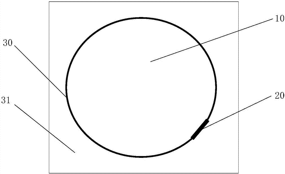
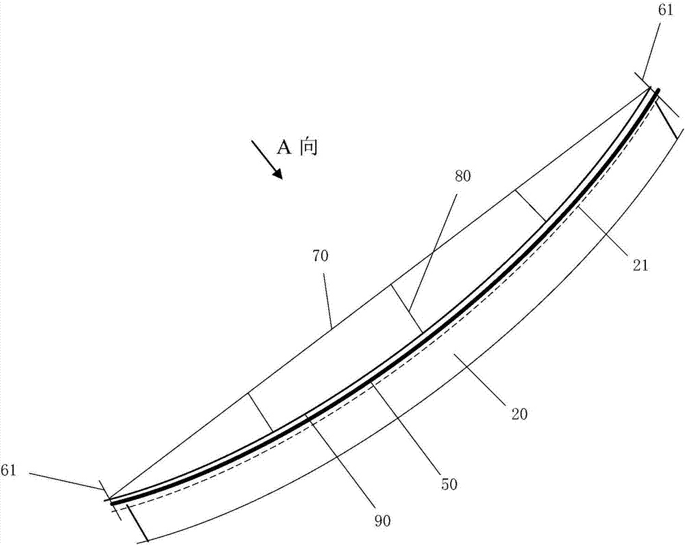
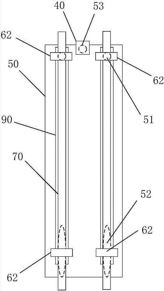
[0025] Such as Figure 1 to Figure 3 As shown, the concrete backfilling device for the anchor groove of the unbonded ring anchor prestressed lining structure of the present invention is used for backfilling the anchor groove 20 on the unbonded ring anchor prestressed lining structure 30 (lining structure for short). . The concrete backfilling device of the present invention includes a pouring formwork 50 and a curvature adjusting member, wherein: the pouring formwork 50 is a bendable flat plate for covering the notch 21 of the anchorage groove 20, and one end of the pouring formwork 50 is a fixed end and the other end It is the adjusting end; the fixed end of the pouring template 50 is provided with a circular fixing hole 51, and the adjusting end is provided with an oval adjusting hole 52, and the fixing hole 51 and the adjusting hole 52 are respectively used to pass through the two ends of the notch 21 of the anchor groove 20. On the embedded part 61; the curvature adjustme...


PUM


Abstract

The invention discloses a concrete backfill device of an anchorage groove of an unbonded ring anchor prestress lining structure and a concrete backfill construction method implemented based on the concrete backfill device. The concrete backfill device comprises a pouring formwork and a bending degree adjusting component. The pouring formwork is used for covering a groove opening of the anchorage groove and a bendable flat plate. A circular fixed hole is formed in the fixed end of the pouring formwork. An elliptical adjusting hole is formed in the adjusting end of the pouring formwork. The fixed hole and the adjusting hole are used for running through embedded pieces at the two ends of the groove opening of the anchorage groove. The bending degree adjusting component comprises a strip-shaped supporting plate and pressing plates. The pressing plates are connected with the two ends of the supporting plate. The middles of the pressing plates and the middle of the supporting plate are connected through adjustable top rods. Installation holes for running through the embedded pieces of the two ends of the groove opening of the anchorage groove are formed in the two ends of the bending degree adjusting component. By means of the concrete backfill device, the concrete backfill of the anchorage groove can be effectively and rapidly achieved in a labor-saving mode, poured concrete is firmand compact, the combination face of new concrete and old concrete is free of cracks, and the coordination consistency with the whole lining structure is good.

Description

technical field [0001] The invention relates to a concrete backfill device applied to an anchor groove of an unbonded ring anchor prestressed lining structure and a concrete backfill construction method based on the concrete backfill device, belonging to the technical field of anchor groove concrete backfill. Background technique [0002] Prestressed lining is generally used in pressurized water delivery tunnels, and ring anchor prestressed lining is a new lining technology to solve the problem of "poor surrounding rock conditions and thin covering layers" for pressurized water delivery tunnels. According to the different contact relationship between prestressed tendons and concrete, the ring-anchored lining can be divided into two types: bonded and non-bonded. Since the 1990s in my country, the ring-anchor prestressed lining structure has been used in pressurized tunnels, and with the construction of large-scale national projects, the construction of large and high-pressure...

Claims


Application Information

Patent Timeline
Patent Type & Authority Applications(China)
IPC IPC(8): E21D20/02E21D11/10
CPCE21D11/105E21D20/021Y02E10/20
Inventor 汪小刚姜龙皮进王玉杰赵宇飞曹瑞琅段庆伟刘立鹏孙平林兴超
Owner CHINA INST OF WATER RESOURCES & HYDROPOWER RES
Why Eureka
Try Eureka