
Separated-type low-voltage power distribution cabinet

A low-voltage power, separated technology, applied in substation/power distribution device housing, electrical components, substation/switch layout details, etc., can solve the problem of affecting the normal operation of equipment in the power distribution cabinet, hindering the staff's sight, and affecting the power distribution cabinet Maintenance and other issues, to achieve the effect of strengthening maintenance and repair, ensuring safe operation, and protecting safe operation

Inactive Publication Date: 2018-04-20
JIAXING HENGJIE ELECTRIC POWER EQUIP INSTALLATION CO LTD
View PDF7 Cites 3 Cited by
  • Summary
  • Abstract
  • Description
  • Claims
  • Application Information

AI Technical Summary

Problems solved by technology

[0002] The power distribution cabinets currently used are all in the form of stainless steel switch bodies. Due to the compact structure inside the power distribution cabinet and the fact that the power distribution cabinet is placed in various environments, the temperature of the power distribution cabinet is relatively high, which seriously affects For the normal operation of the equipment in the power distribution cabinet, the accuracy is greatly reduced, and even a short circuit may occur. In addition, the various staggered cables in the power distribution cabinet hinder the sight of the staff and greatly affect the staff Maintenance of distribution cabinets

Method used


Image

  • Separated-type low-voltage power distribution cabinet
  • Separated-type low-voltage power distribution cabinet
  • Separated-type low-voltage power distribution cabinet

Examples


Embodiment Construction

[0019] In order to make the technical means, creative features, goals and effects achieved by the present invention easy to understand, the present invention will be further described below in conjunction with specific embodiments.

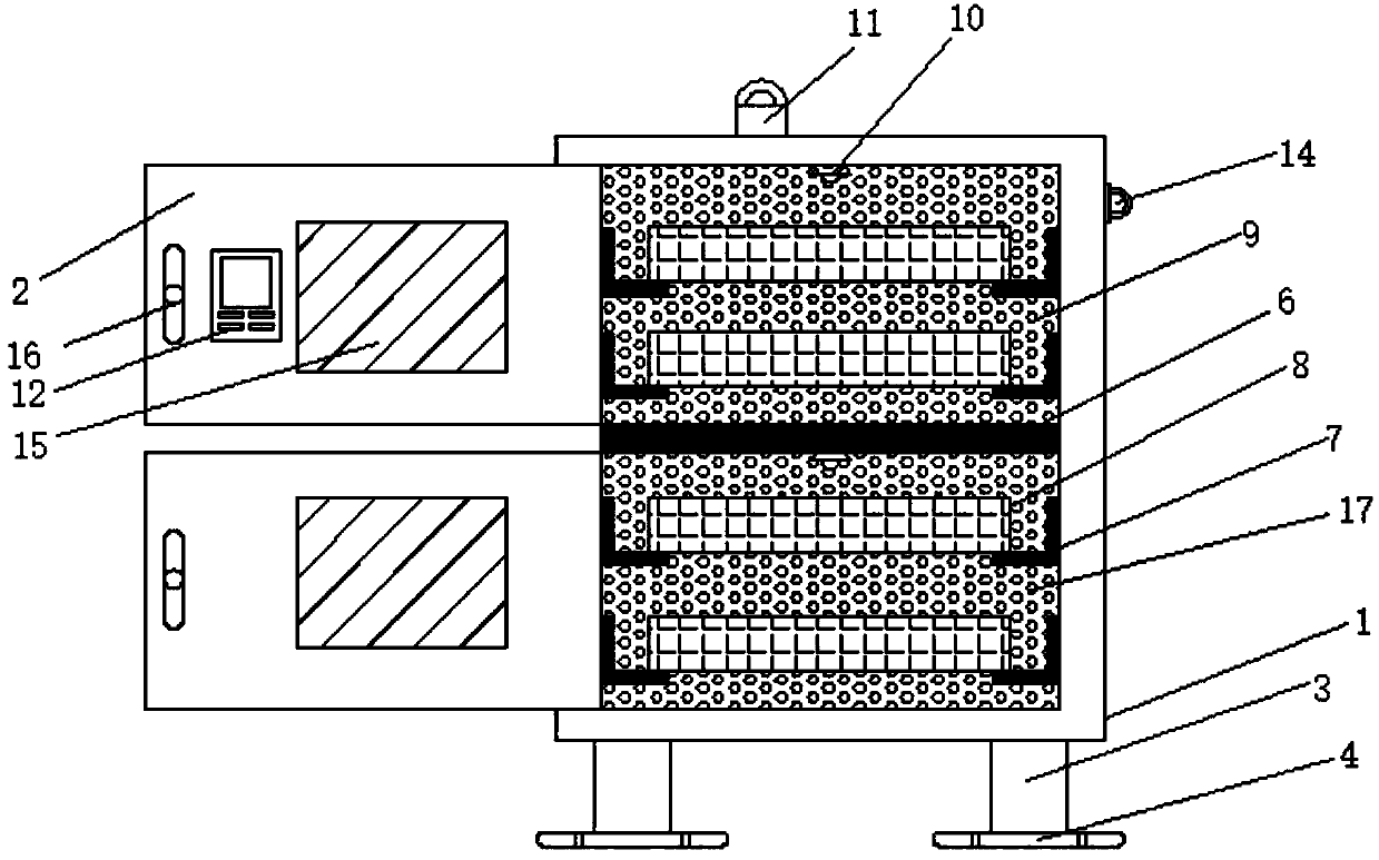
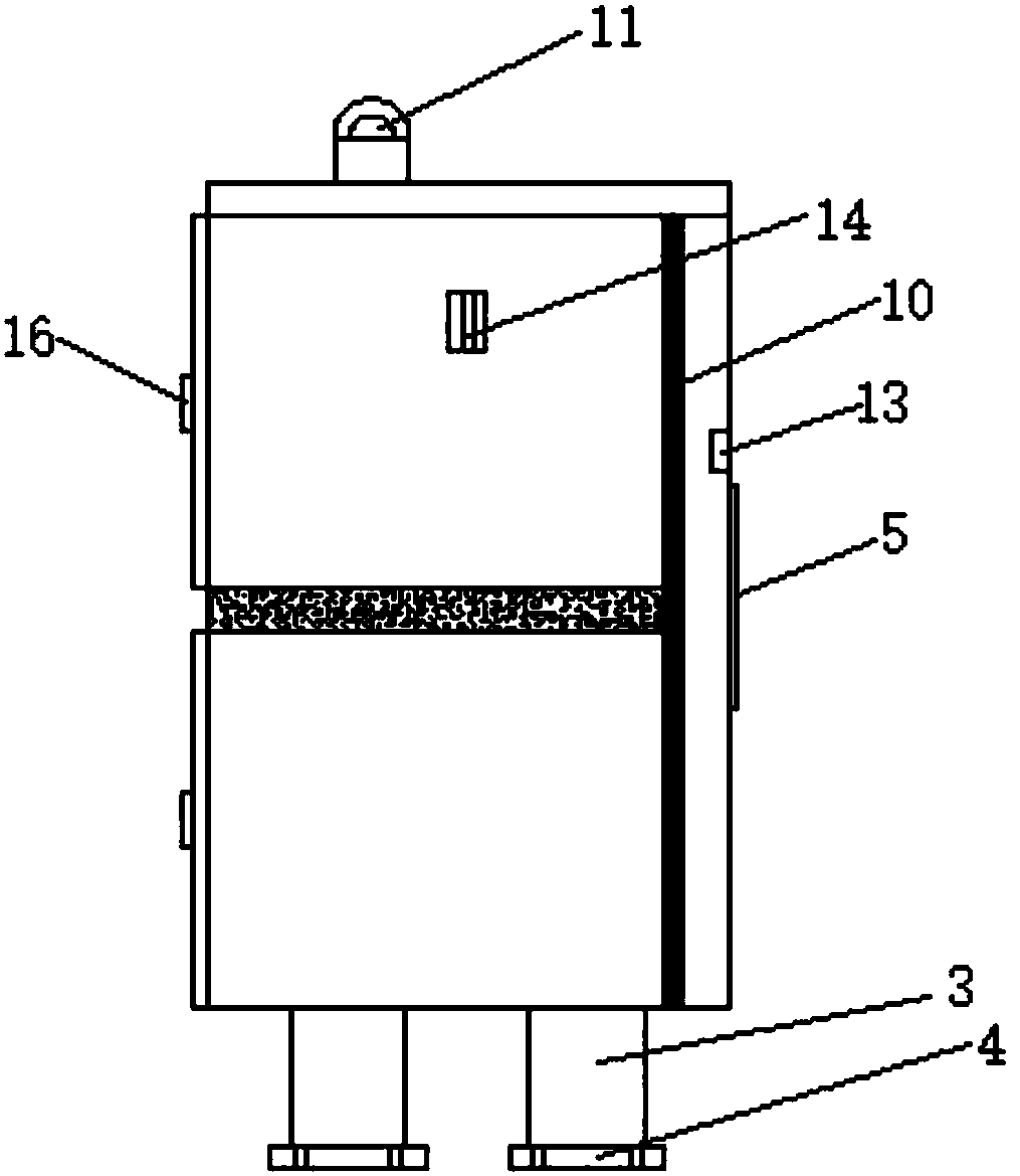
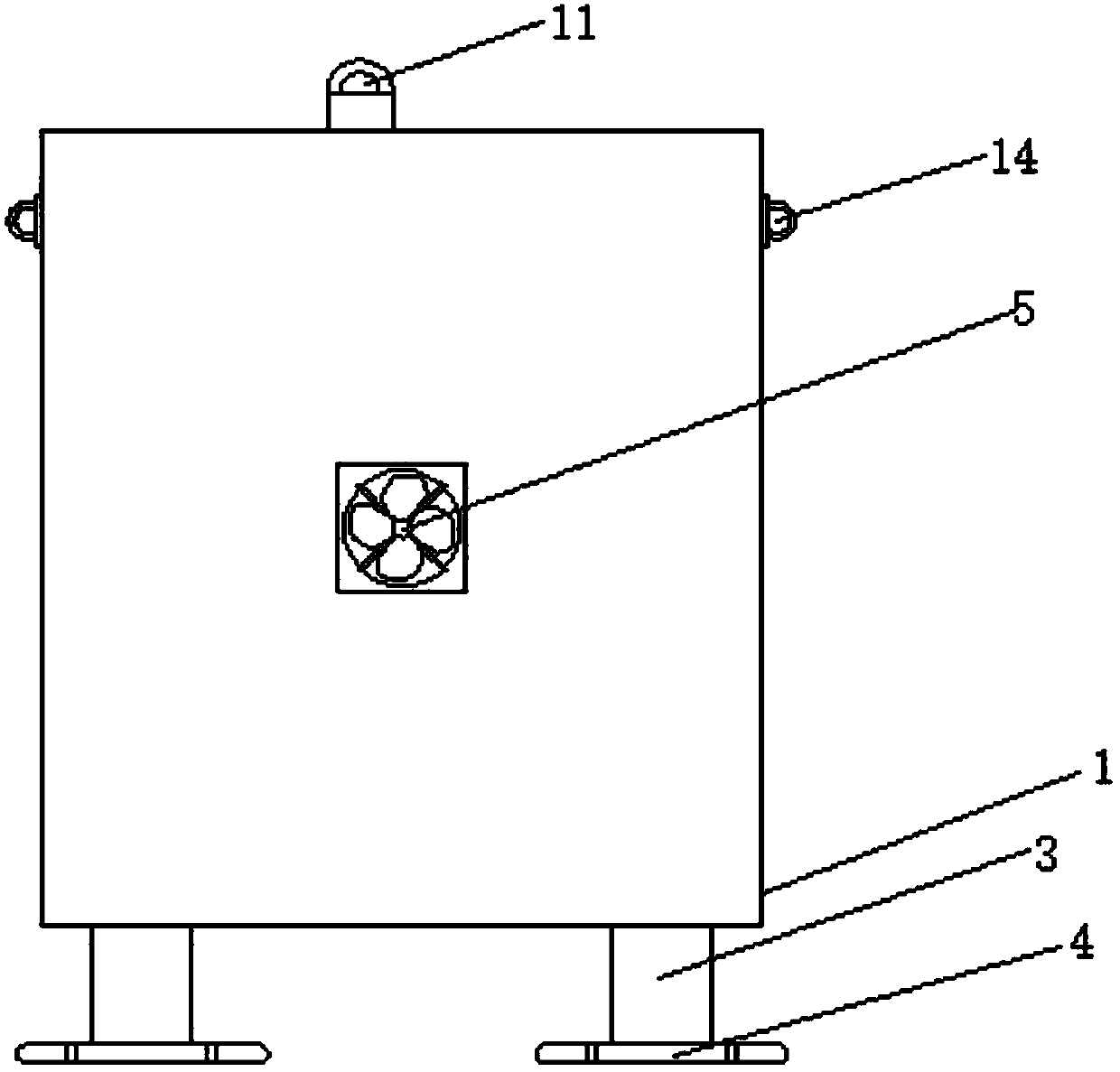
[0020] Such as Figure 1-3 As shown, a partitioned low-voltage power distribution cabinet includes a cabinet body 1, a cabinet door 2, a support column 3 and a partition plate 6. One side of the cabinet body 1 is hinged to a cabinet door 2, and the cabinet body 1 The bottom is fixedly welded with a support column 3, the inner wall of the cabinet body 1 is fixedly connected with a partition plate 6, the bottom of the support column 3 is fixedly welded with a bottom plate 4, the back of the cabinet body 1 is fixedly connected with a cooling fan 5, and the cabinet body 1 is fixedly connected with a cooling fan 5. Both sides of the inner wall of the body 1 are fixedly connected with an antistatic partition 7, one side of the antistatic partition 7 is ...


PUM


Abstract

The invention discloses a separated-type low-voltage power distribution cabinet, which comprises a cabinet body, a cabinet door, support columns and a separation plate. The cabinet door is hinged at one side of the cabinet body; the support columns are fixedly welded to the bottom portion of the cabinet body; and the inner wall of the cabinet body is fixedly connected with the separation plate. Abottom plate is fixedly welded to the bottom portion of each support column. The back surface of the cabinet body is fixedly connected with a radiator fan. The two sides of the inner wall of the cabinet body are respectively and fixedly connected with an anti-static separator plate. One side of each anti-static separator plate is fixedly connected with a device installation groove. One side of each device installation groove is fixedly connected with a radiating plate. The inner wall top portion of the cabinet body and the bottom portion of the separator plate are respectively and fixedly connected with an LED lamp. The outer wall top portion of the cabinet body is fixedly connected with an alarm. Through the separator plate, the cabinet body can be separated effectively; through the radiating plates and the radiator fan, the heat in the cabinet body can be effectively dissipated, thereby protecting operation of the device; and through the LED lamps, later maintenance and repair can berealized conveniently.

Description

technical field [0001] The invention relates to the field of power distribution cabinets, in particular to a separated low-voltage power distribution cabinet. Background technique [0002] The power distribution cabinets currently used are all in the form of stainless steel switch bodies. Due to the compact structure inside the power distribution cabinet and the fact that the power distribution cabinet is placed in various environments, the temperature of the power distribution cabinet is relatively high, which seriously affects For the normal operation of the equipment in the power distribution cabinet, the accuracy is greatly reduced, and even a short circuit may occur. In addition, the various staggered cables in the power distribution cabinet hinder the sight of the staff and greatly affect the staff Maintenance of distribution cabinets. To this end, we propose a separate low-voltage power distribution cabinet. Contents of the invention [0003] The main purpose of t...

Claims


Application Information

Patent Timeline
Patent Type & Authority Applications(China)
IPC IPC(8): H02B1/56H02B1/30H02B1/38
CPCH02B1/565H02B1/30H02B1/303H02B1/38
Inventor 陆龙杰李芳
Owner JIAXING HENGJIE ELECTRIC POWER EQUIP INSTALLATION CO LTD
Learn More