
Multi-core optical fiber resonant cavity gas sensor

A gas sensor and multi-core optical fiber technology, applied in the field of optics, can solve problems such as difficult to apply on-site detection, difficult remote detection, complex test system, etc.

Pending Publication Date: 2018-04-20
CAPITAL NORMAL UNIVERSITY
View PDF6 Cites 2 Cited by
  • Summary
  • Abstract
  • Description
  • Claims
  • Application Information

AI Technical Summary

Problems solved by technology

[0003] The traditional whispering gallery mode microcavity sensor test system is complex, it is difficult to apply to on-site detection, and it is difficult to realize remote detection

Method used


Image

  • Multi-core optical fiber resonant cavity gas sensor
  • Multi-core optical fiber resonant cavity gas sensor
  • Multi-core optical fiber resonant cavity gas sensor

Examples


Embodiment Construction

[0040] The technical solution of the present application will be described in further detail below with reference to the drawings and embodiments.

[0041] In order to make the purpose, technical solution and advantages of the present application clearer, the multi-core fiber resonant cavity gas sensor of the present application will be further described in detail below with reference to the drawings and embodiments. It should be understood that the specific embodiments described here are only used to explain the present application, not to limit the present application.

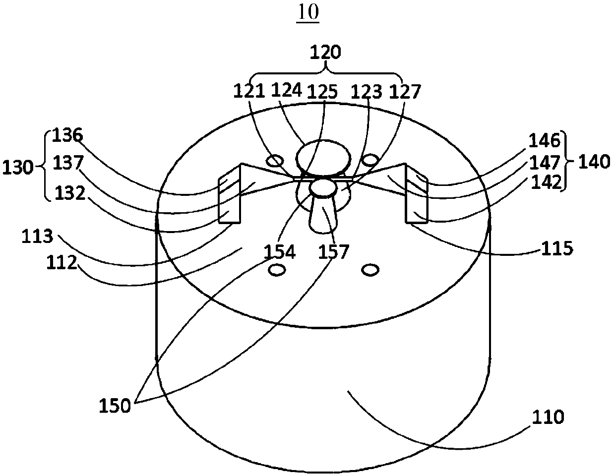
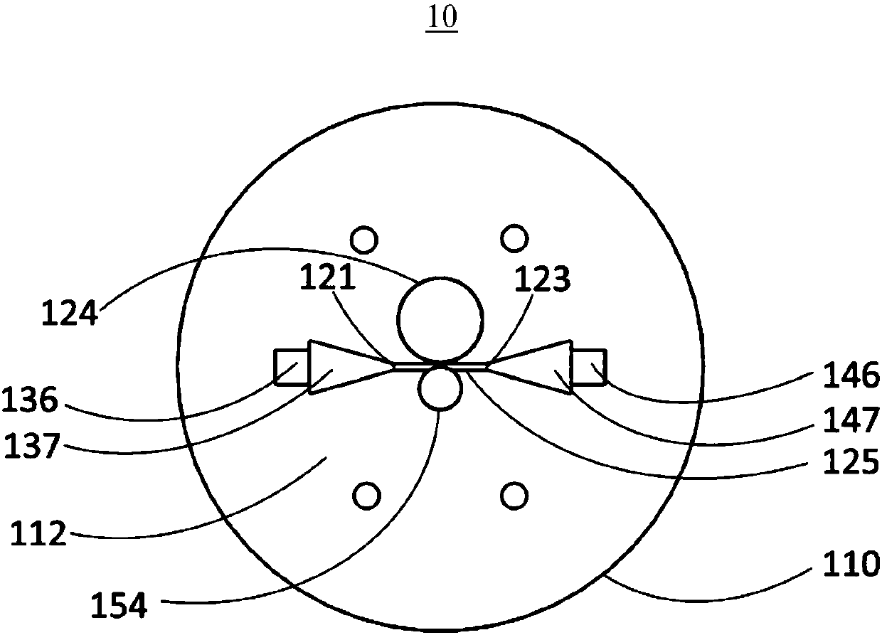
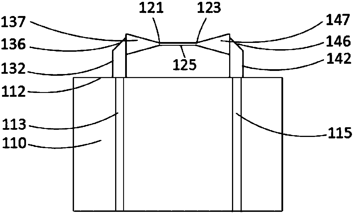
[0042] See Figure 1-3 , the embodiment of the present application provides a multi-core fiber resonator gas sensor 10 , including a multi-core fiber 110 , an optical resonance device 120 , a first light guiding structure 130 and a second light guiding structure 140 . The multi-core optical fiber 110 includes a plurality of optical fiber cores. The first light guiding structure 130 optically connects one f...


PUM

PropertyMeasurementUnit
diameteraaaaaaaaaa
lengthaaaaaaaaaa

Abstract

The invention relates to a multi-core optical fiber resonant cavity gas sensor which comprises a multi-core optical fiber, an optical resonant device, a first light guide structure and a second lightguide structure, wherein the multi-core optical fiber comprises a first optical fiber core and a second optical fiber core, and is provided with an end surface; the first optical fiber core and the second optical fiber core are exposed out from the end surface; the optical resonant device is arranged on the end surface and provided with a light input end and a light output end; the first light guide structure is arranged on the end surface, is connected with the first optical fiber core and the light input end, and is used for inputting light of the first optical fiber core into the optical resonant device; the second light guide structure is arranged on the end surface, i connected with the second optical fiber core and the light output end, and used for coupling light of the optical resonant device and outputting the light from the second optical fiber core.

Description

technical field [0001] The present application relates to the field of optics, in particular to a multi-core optical fiber resonant cavity gas sensor. Background technique [0002] Whispering gallery mode microresonator is a kind of optical microcavity. Its typical feature is that the refractive index of the material constituting the microcavity is greater than the refractive index of the external environment. Due to the total reflection, the light wave propagates along the ring in the microcavity. When the conditions are met, a stable light wave mode, that is, the whispering gallery mode, can be formed. Generally speaking, any structure that can form a closed ring optical path can be used as a microcavity, and the geometric shape of the microresonator can be a disc, a sphere, a ring, and a micropipe. The whispering gallery mode microresonator with a smooth appearance made of low absorption loss materials can effectively suppress the absorption loss and scattering loss of l...

Claims


Application Information

Patent Timeline
Patent Type & Authority Applications(China)
IPC IPC(8): G01N21/25
CPCG01N21/25G01N21/255
Inventor 冯胜飞张思瑶张岩
Owner CAPITAL NORMAL UNIVERSITY
Learn More