
Negative pressure valve and water dispenser with negative pressure valve

A negative pressure valve and valve core technology, applied in the valve operation/release device, sliding valve, valve details and other directions, can solve the problems of high cost, difficulty in enterprise development, and high development cost, and achieve low manufacturing costs and reduced development costs. Difficulty, development cost, and long service life

Pending Publication Date: 2018-04-20
GUANDDONG JIBAO ELECTRICAL APPLIANCE TECH CO LTD
View PDF0 Cites 2 Cited by
  • Summary
  • Abstract
  • Description
  • Claims
  • Application Information

AI Technical Summary

Problems solved by technology

[0002] Water dispensers usually include two types of water tanks and no water tanks. The water source with a water tank is usually without pressure, so it needs to be supplied by a booster pump. The booster pump has a short life and is difficult to use in commercial occasions; Ordinary water pumps can be used for water supply, but due to the need to adjust the flow, it is necessary to install additional flow regulating valves and check valves, which are complex in structure and high in cost
[0003] The water supply part of the above two types of water dispensers cannot be used in common, which makes the development of enterprises difficult and costly

Method used


Image

  • Negative pressure valve and water dispenser with negative pressure valve
  • Negative pressure valve and water dispenser with negative pressure valve
  • Negative pressure valve and water dispenser with negative pressure valve

Examples


Embodiment Construction

[0022] The present invention will be further described below in conjunction with the accompanying drawings and embodiments.

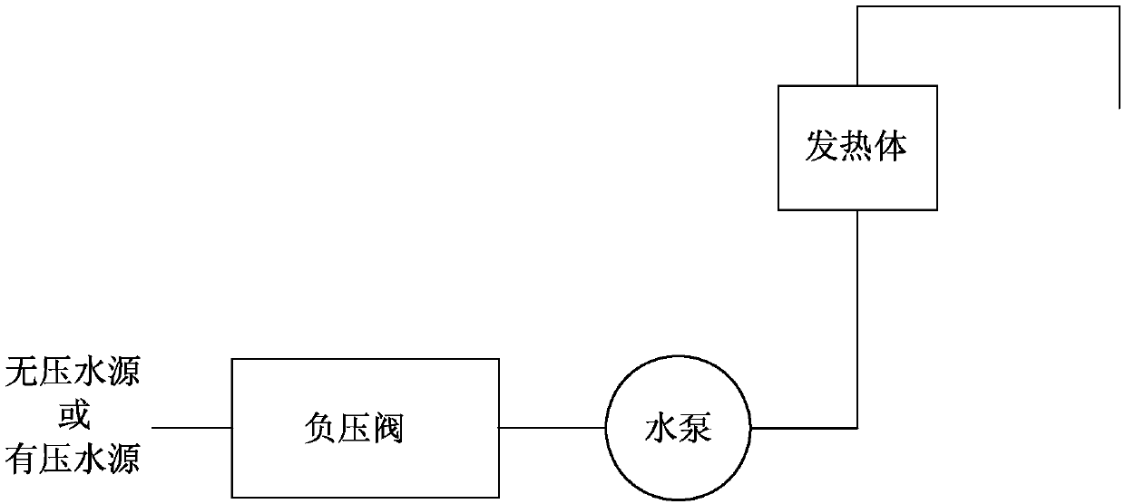
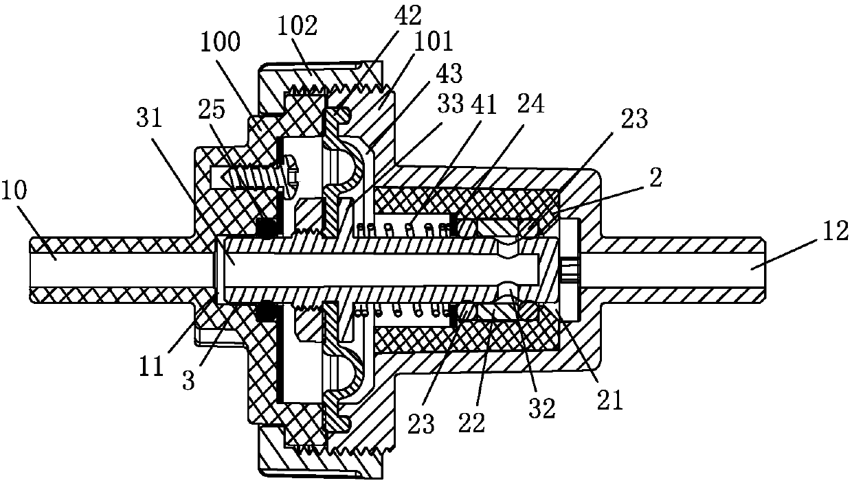
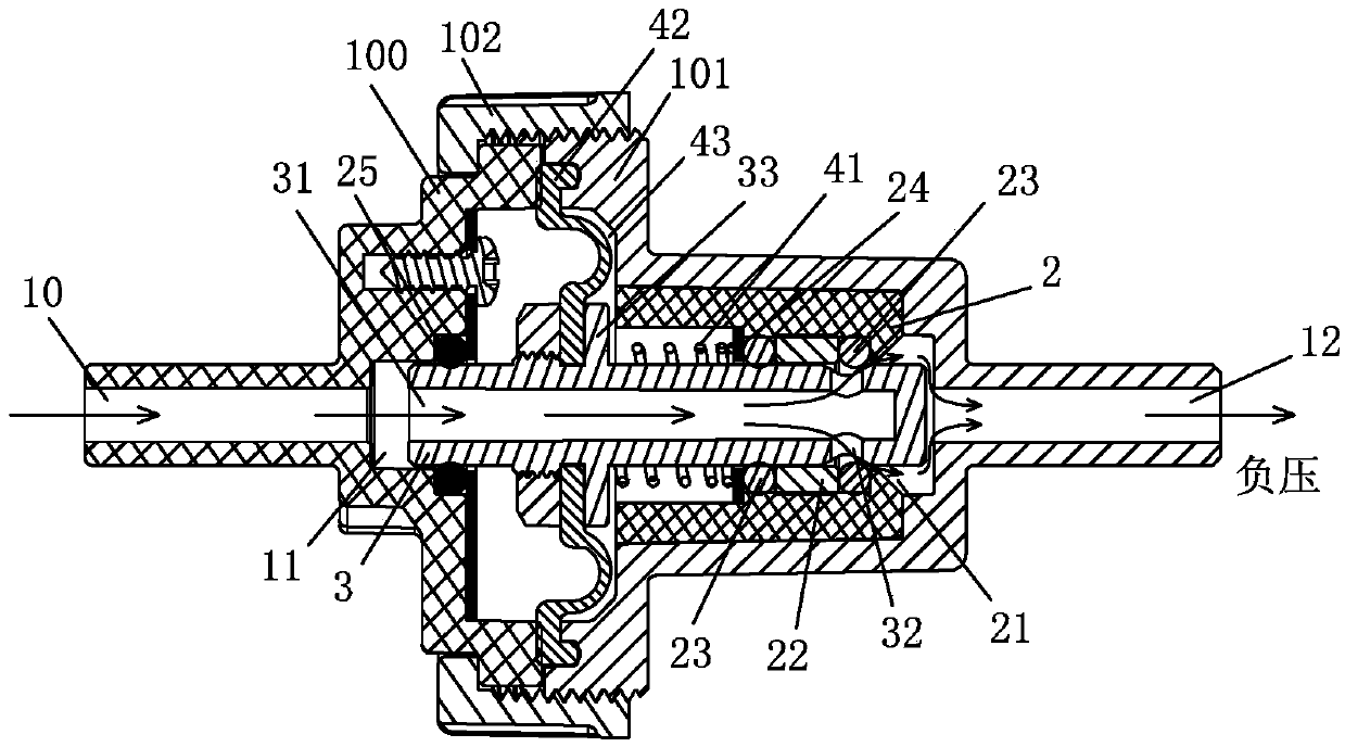
[0023] see Figure 2-3 , the negative pressure valve includes a valve body with a water inlet 10, a valve cavity 11 and a water outlet 12 in the axial direction. There is a piston rod 3, the valve core 2 is axially provided with an opening 21 communicating with the water outlet 12, the piston rod 3 is a hollow tube, one end of which is provided with a water inlet 31 communicating with the water inlet 10, The other end is provided with a water outlet 32, and the piston rod 3 is axially elastically slid and arranged in the valve core 2; image 3 As shown in the water supply state of the negative pressure valve, when the water inlet 10 generates negative pressure, the piston rod 3 slides axially toward the water outlet 12, and the water outlet 32 ​​communicates with the opening 21. By adjusting the size of the negative pressure, the piston rod 3 can be co...


PUM


Abstract

The invention discloses a negative pressure valve. The valve comprises a valve body axially provided with a water inlet end, a valve cavity and a water outlet end, a valve element is arranged in the valve cavity, a piston rod is movably arranged in the valve element, an opening communicated with the water outlet end is axially formed in the valve element, the piston rod is a hollow pipe, one end of the piston rod is provided with a water inlet communicated with the water inlet end, the other end of the piston rod is provided with a water outlet, and the piston rod is axially and elastically arranged in the valve element in a sliding manner. The invention further discloses a water dispenser comprising the negative pressure valve. When the water outlet end of the negative pressure valve generates the negative pressure, the piston rod can be movably opened, water supply of the water dispenser is achieved, the opening amplitude of the piston rod is decided by negative pressure, the needs of adjusting the water outlet flow are met, when the negative pressure disappears, the water outlet end of the negative pressure valve recovers to the normal pressure, the piston rod is movably closed,water supply to the water dispenser is stopped, and the flow stop effect is achieved.

Description

technical field [0001] The invention relates to the field of water dispensers, in particular to a negative pressure valve used in a water dispenser and a water dispenser with the negative pressure valve. Background technique [0002] Water dispensers usually include two types of water tanks and no water tanks. The water source with a water tank is usually without pressure, so it needs to be supplied by a booster pump. The booster pump has a short life and is difficult to use in commercial occasions; It is sufficient to use an ordinary water pump for water supply, but because the flow needs to be adjusted, an additional flow regulating valve and a one-way valve need to be installed, which has a complicated structure and high cost. [0003] The water supply parts of the above two types of water dispensers cannot be used in common use, which leads to great difficulty and high development cost for enterprises. Contents of the invention [0004] The purpose of the present inve...

Claims


Application Information

Patent Timeline
Patent Type & Authority Applications(China)
IPC IPC(8): F16K31/122F16K3/30
CPCF16K3/30F16K31/122
Inventor 佘群
Owner GUANDDONG JIBAO ELECTRICAL APPLIANCE TECH CO LTD
Learn More