
Intelligent fan electronic control box

A technology of electric control box and fan, which is applied in the field of electric control box, can solve the problems affecting the working stability and service life of the electric control box of the fan, the safety protection of the fan equipment is not perfect, and there is no effective protection, so as to achieve perfect and reliable protection function , Accelerate the air flow and prolong the service life

Pending Publication Date: 2018-04-20
DONGGUAN GUOTONG VENTILATION EQUIP
View PDF0 Cites 1 Cited by
  • Summary
  • Abstract
  • Description
  • Claims
  • Application Information

AI Technical Summary

Problems solved by technology

Although the existing fan electric control box can meet the needs of ordinary start-up, stop and other processes, it is not perfect in terms of safety protection for the use of fan equipment. The traditional fan electric control box is still not suitable for unexpected light or heavy loads Without effective protection, there is still room for improvement
In addition, although the traditional fan electric control box has cooling holes, the fan electric control box is generally installed on the fan body or near the fan. Since the electrical components will generate heat when they are working, the heat will accumulate in the fan electric control box. It is not easy to disperse, which affects the working stability and service life of the fan electric control box

Method used


Image

  • Intelligent fan electronic control box
  • Intelligent fan electronic control box
  • Intelligent fan electronic control box

Examples


Embodiment Construction

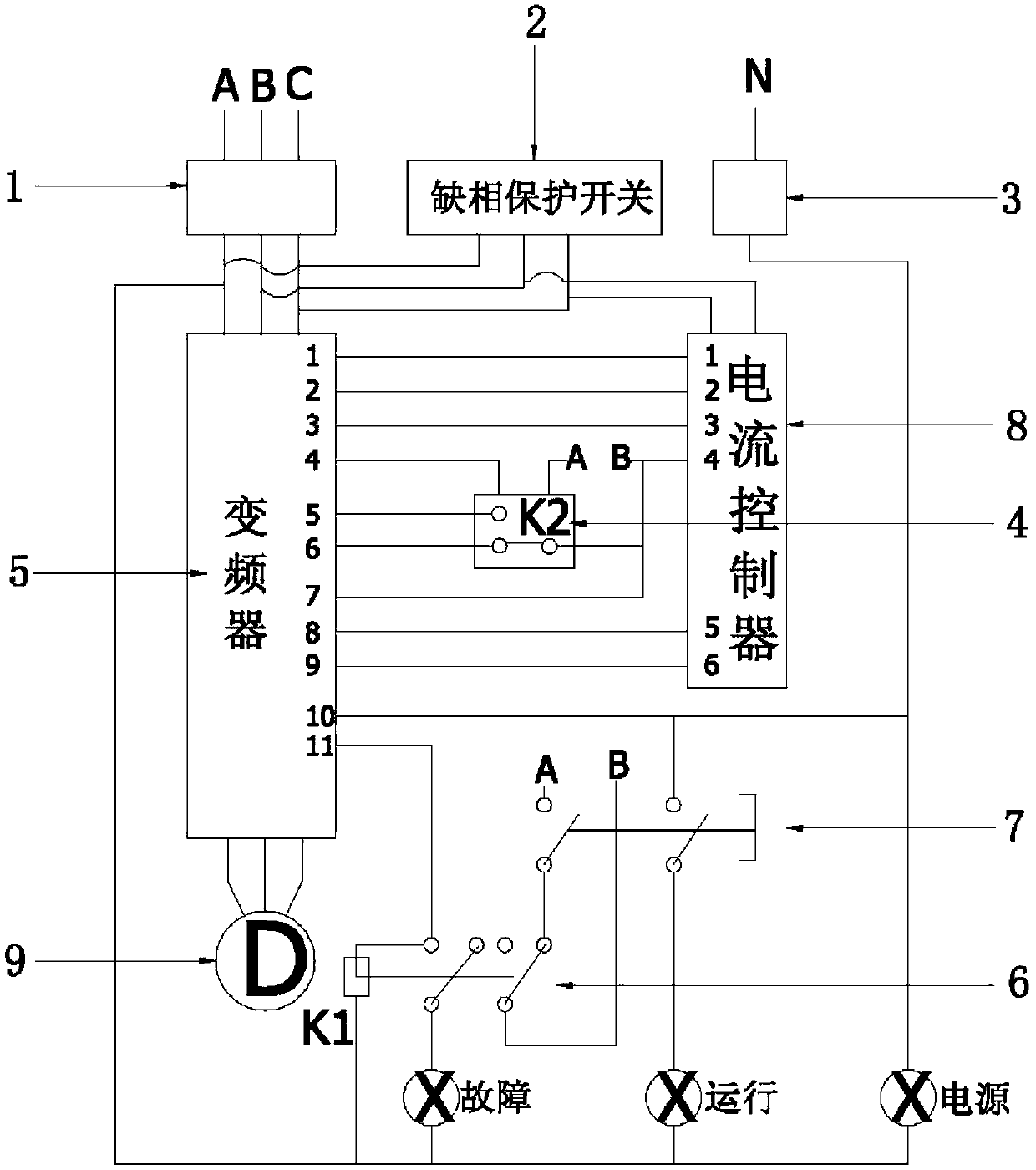
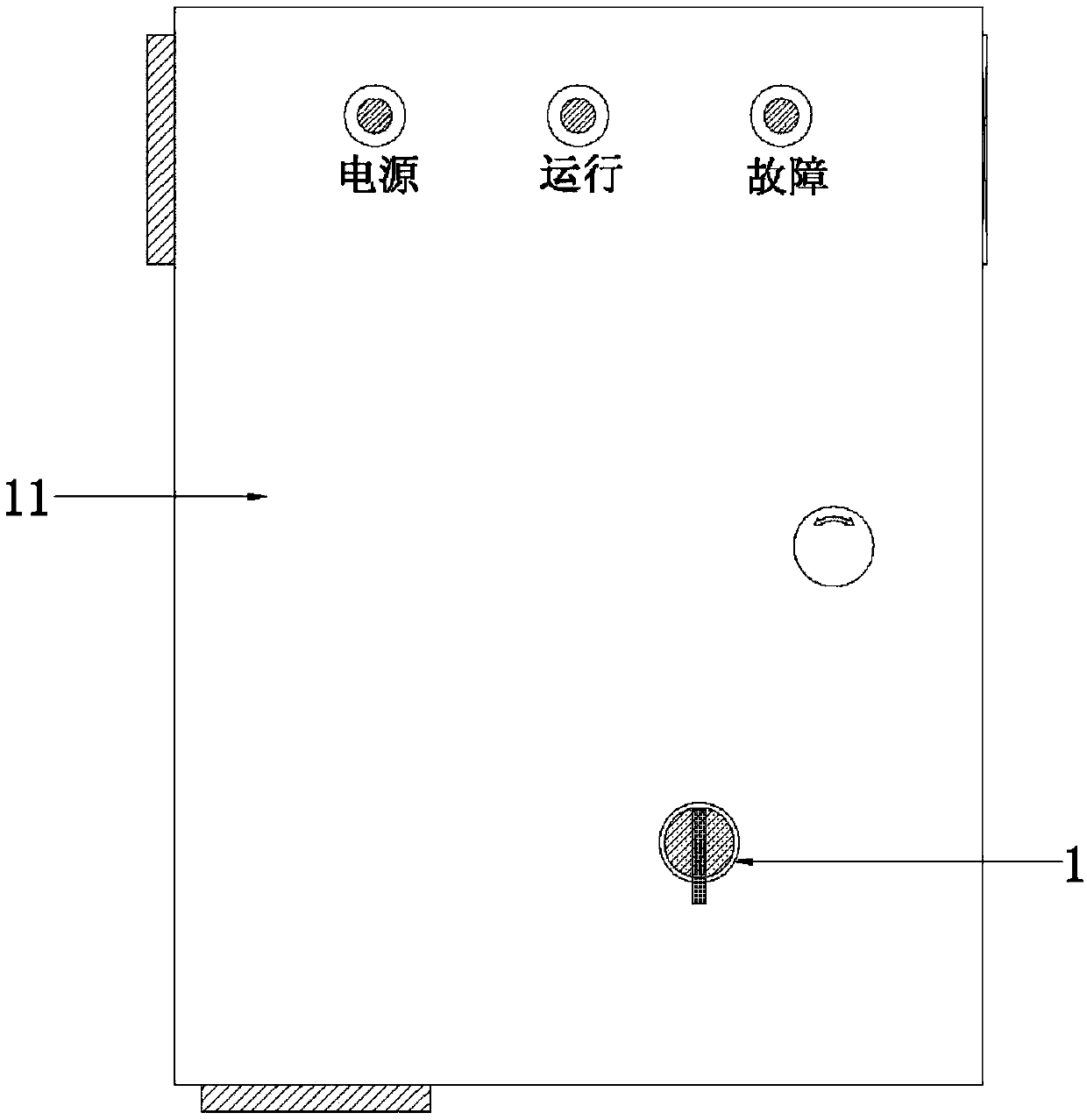
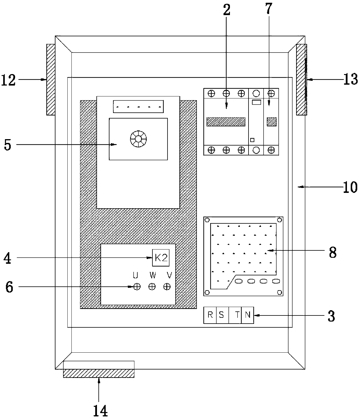
[0016] Examples, see figure 1 , figure 2 and image 3 , an electric control box for an intelligent fan provided in this embodiment, which includes a box body 10 and a main power switch 1 arranged on the box body 10, a phase loss protection switch 2, a neutral line input switch 3, and a breaker 4 (Fig. Indicated by K2), frequency converter 5, fault output relay unit 6, panel switch group 7 and current controller 8, current controller 8 is connected with main power switch 1, phase loss protection switch 2, breaker 4 and frequency converter respectively 5 phases are connected, the frequency converter 5 is connected with the load equipment 9 to be controlled (namely the fan), and the panel switch group 7 is connected with the fault output relay unit 6, the zero line input switch 3 and the frequency converter 5 respectively. Specifically, the fault output relay unit 6 includes a fault output relay (indicated by K1 in the figure) and a fault indicator light connected to the fault...


PUM


Abstract

The invention discloses an intelligent fan electronic control box. The intelligent fan electronic control box comprises a box body, a power master switch, a lack-phase protection switch, a frequency converter, a fault output relay unit, a panel switching group and a current controller, wherein the power master switch, the lack-phase protection switch, the frequency converter, the fault output relay unit, the panel switching group and the current controller are arranged on the box body; the current controller is connected with the power master switch, the lack-phase protection switch and the frequency converter separately; the frequency converter is connected with load equipment which requires to be controlled; and the panel switching group is connected with the fault output relay unit andthe frequency converter separately. The intelligent fan electronic control box is skillful and reasonable in structural design; in a working process, when load power is set, the frequency converter can correspondingly transmit frequency increasing or frequency reducing signals according to the magnitude of running current, the frequency converter automatically and stably runs in the set load power, when in accidental heavy load or idle load, the speed of the controller can be automatically reduced or increased, a perfect and reliable protection function is fulfilled, normal operation of a fanis ensured effectively, and the service life of the fan is prolonged; and moreover, the heat dissipation effect is good, it can be ensured that the working temperature of the electronic control box iscontrolled in a set range, and the service life of the electronic control box is prolonged.

Description

technical field [0001] The invention relates to the technical field of electric control boxes, in particular to an intelligent fan electric control box for controlling fans. Background technique [0002] As we all know, the fan needs to be controlled by the fan control box during the start and stop process. Although the existing fan electric control box can meet the needs of ordinary start-up, stop and other processes, it is not perfect in terms of safety protection for the use of fan equipment. The traditional fan electric control box is still not suitable for unexpected light or heavy loads Without effective protection, there is still room for improvement. In addition, although the traditional fan electric control box has cooling holes, the fan electric control box is generally installed on the fan body or near the fan. Since the electrical components will generate heat when they are working, the heat will accumulate in the fan electric control box. It is not easy to dis...

Claims


Application Information

Patent Timeline
Patent Type & Authority Applications(China)
IPC IPC(8): F04D27/00F04D29/58
CPCF04D27/00F04D27/001F04D27/004F04D29/5813
Inventor 聂福坚
Owner DONGGUAN GUOTONG VENTILATION EQUIP
Learn More