Eureka AIR delivers breakthrough ideas for toughest innovation challenges, trusted by R&D personnel around the world.

Immersed tunnel final joint and butt-joint construction method thereof

An immersed tube tunnel and construction method technology, applied in artificial islands, water conservancy projects, infrastructure engineering, etc., can solve problems that threaten the life safety of constructors, require extremely high construction accuracy, and cannot achieve reversible construction, so as to reduce construction costs. Risk, high construction efficiency, and the effect of reducing the probability of failure

Pending Publication Date: 2018-04-20
NO 2 ENG CO LTD OF CCCC FIRST HARBOR ENG +1
View PDF0 Cites 6 Cited by
  • Summary
  • Abstract
  • Description
  • Claims
  • Application Information

AI Technical Summary

Problems solved by technology

However, the safety period provided by the temporary water-stop environment that uses jacks to maintain pressure is only 30 days at most. If the welding of the steel plate cannot be completed within 30 days to achieve permanent water-stop, the temporary water-stop will fail and cause serious losses. Moreover, during construction , if the temporary water stop fails due to an accident, it will directly threaten the life safety of the constructor. Therefore, the construction risk of the final joint of the existing immersed tunnel is huge
In addition, the final joints of existing immersed tunnels cannot achieve reversible construction, which requires extremely high construction accuracy

Method used


Image

  • Immersed tunnel final joint and butt-joint construction method thereof
  • Immersed tunnel final joint and butt-joint construction method thereof
  • Immersed tunnel final joint and butt-joint construction method thereof

Examples


Embodiment Construction

[0029] In the following, the present invention will be specifically described through exemplary embodiments. It should be understood, however, that elements, structures and characteristics of one embodiment may be beneficially incorporated in other embodiments without further recitation.

[0030] In the description of the present invention, it should be noted that the orientation or positional relationship indicated by the terms "inner", "outer", "top", "bottom", "front", "rear" etc. are based on the attached figure 1 The positional relationship shown is only for the convenience of describing the present invention and simplifying the description, but does not indicate or imply that the referred device or element must have a specific orientation, be constructed and operated in a specific orientation, and therefore cannot be construed as limiting the present invention . In addition, the terms "first" and "second" are used for descriptive purposes only, and should not be underst...


PUM


Abstract

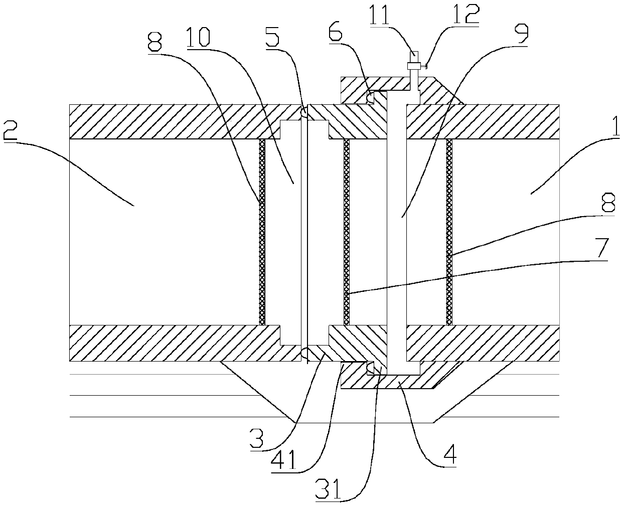
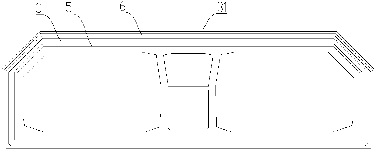
The invention provides an immersed tunnel final joint and a butt-joint construction method thereof and belongs to the technical field of immersed tunnel construction. According to the immersed tunnelfinal joint, temporary water stop is achieved through the water pressure, the construction risk can be effectively lowered, and reversible construction can be achieved. The immersed tunnel final jointcomprises a pushing pipe segment and a connecting pipe segment, wherein the connecting pipe segment is used for being connected with the pushing pipe segments. The connecting pipe segment is prefabricated to an end, waiting for butt joint, of a final pipe segment. The pushing pipe segment is connected into the connecting pipe segment in a sleeved manner. The end, backing against the final pipe segment, of the pushing pipe segment can extend out of the connecting pipe segment and is in butt joint with an end, waiting for butt joint, of a mounted pipe segment in a matched manner. The end face of the extendable end of the pushing pipe segment is provided with a first water stop belt. The pushing pipe segment is internally provided with a seal door. A water storage cavity is formed by the seal door, the pipe wall of the connecting pipe segment and end seal doors arranged at the end, waiting for butt joint, of the final pipe segment, wherein water can be stored in the water storage cavity.

Description

technical field [0001] The invention belongs to the technical field of immersed tube tunnel construction, and in particular relates to a final joint of an immersed tube tunnel and a butt joint construction method thereof. Background technique [0002] In the installation of the pipe section of the immersed tube tunnel, in order to make the last pipe section sink smoothly, a space longer than the distance of the pipe section must be reserved. After the last pipe section is lowered, the end surface of the last pipe section needs to be connected with the previous pipe section through a connection structure, which is the final joint. [0003] At present, the final joint of commonly used immersed tube tunnels usually adopts push-type water-stop for temporary water-stop. Specifically, several jacks installed in the steel structure of the final joint simultaneously push out the push-up beams, and then achieve temporary water-stop through jack pressure maintenance. water. However,...

Claims


Application Information

Patent Timeline
IPC IPC(8): E02D29/073E02D29/16E02D31/02
CPCE02D29/073E02D29/16E02D31/02
Inventor 刘德进苏长玺冯海暴张乃受冯甲鑫马宗豪曲俐俐张学俊
Owner NO 2 ENG CO LTD OF CCCC FIRST HARBOR ENG
Why Eureka
Eureka Blog
Learn More