Method for the homogeneous non-contact cooling of hot, non-endless surfaces and device therefor

A cooling device, non-contact technology, applied in the direction of workpiece cooling device, workpiece heating device, quenching device, etc., can solve problems such as becoming problematic, unsuitable, expensive cooling system, etc.

Active Publication Date: 2018-04-17
VOESTALPINE STAHL GMBH
View PDF4 Cites 3 Cited by
  • Summary
  • Abstract
  • Description
  • Claims
  • Application Information

AI Technical Summary

Problems solved by technology

[0003] Existing cooling systems are either very expensive or kept very simple, for example by blowing air or other fluids, such as water or oil; this has the disadvantage that unfavorable, uncontrolled flow conditions always occur on the surface, and then This becomes a problem when specially defined cooling is required
[0006] Particular difficulty exists if there are different material thicknesses on the cooling surfaces to be cooled to a uniform temperature regime

Method used


Image

  • Method for the homogeneous non-contact cooling of hot, non-endless surfaces and device therefor
  • Method for the homogeneous non-contact cooling of hot, non-endless surfaces and device therefor
  • Method for the homogeneous non-contact cooling of hot, non-endless surfaces and device therefor

Examples


Embodiment Construction

[0037] One possible implementation will be described below.

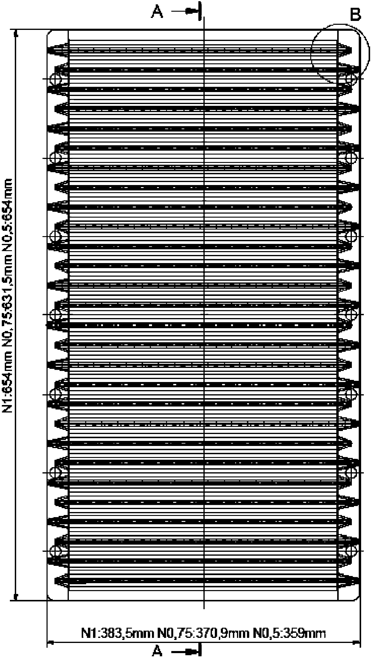
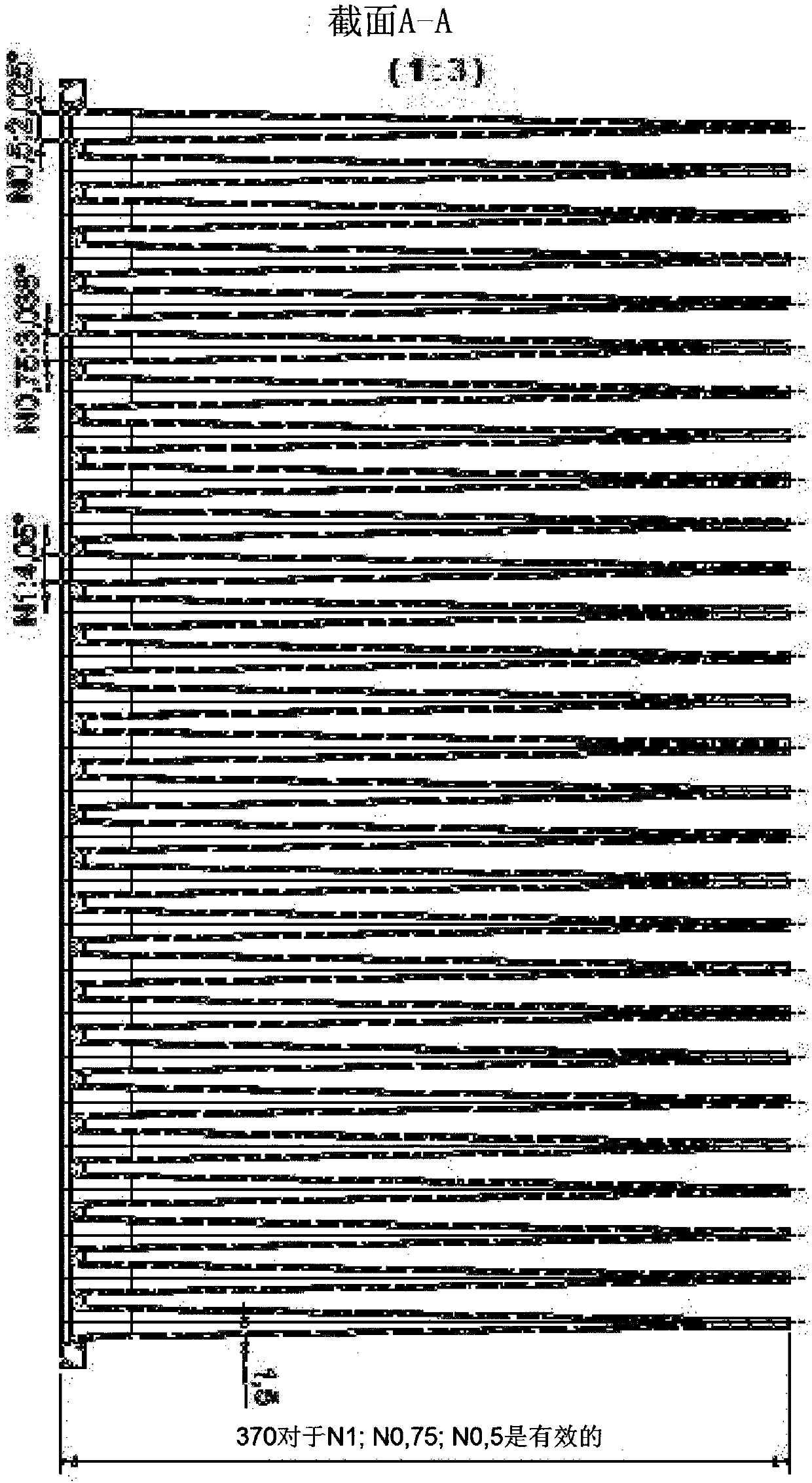
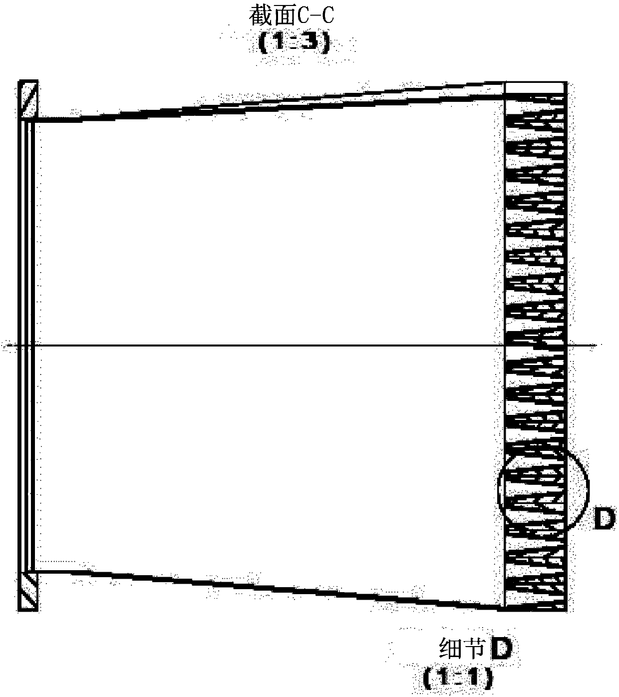
[0038] The cooling device 1 according to the invention has at least one cooling blade 2 . The cooling blade 2 is realized in the form of an elongated airfoil and has a cooling blade base 3, two cooling blade broadsides 4 extending away from the cooling blade base, two cooling blade narrowsides 5 connecting the cooling blade broadsides, and the free nozzle edge 6 .

[0039] The cooling vane 2 is realized as a hollow body with a cooling vane cavity 7 ; Using the cooling blade base 3, the cooling blades are inserted into the cooling blade frame 8; and the cooling blade frame 8 can be placed on the hollow fluid supply tank.

[0040] The area of ​​the nozzle edge 6 is provided with a plurality of nozzles or openings which reach into the cavity 7 and thus allow fluid to flow out of the cavity to the outside through the nozzle 10 .

[0041] Nozzle ducts 11 extend from the nozzles into the chamber 7 , spatially separatin...


PUM


Abstract

The present invention relates to a device for cooling hot objects, in particular a device for the homogeneous, non-contact cooling of hot, primarily non-endless surfaces, wherein the device for cooling comprises at least a cooling blade or a cooling cylinder, the cooling blade or the cooling cylinder having a hollow design and a cooling blade nozzle edge or a plurality of serially arranged coolingcylinders. At least one nozzle is provided in the nozzle edge, which is directed to an object to be cooled, wherein at least seven cooling blades are arranged in such a manner that the flow image onthe surface to be cooled forms a honeycomb-like structure. The invention also relates to a method therefor.

Description

technical field [0001] The present invention relates to a method for uniform non-contact cooling of hot predominantly non-infinite surfaces and a device for the method. Background technique [0002] In the state of the art, cooling processes are required in many areas, for example when cooling of flat panels is required, but also when cooling of glass surfaces (eg in glassmaking) or cooling of processor units etc. is required. [0003] Existing cooling systems are either very expensive or kept very simple, for example by blowing air or other fluids, such as water or oil; this has the disadvantage that unfavorable, uncontrolled flow conditions always occur on the surface, and then This becomes a problem when specifically defined cooling is required. [0004] In the prior art, it had to be largely assumed that unfavorable flow conditions (so-called cross-flows) exist on the flat surface to be cooled and that this leads to non-uniform surface temperatures. This is particularl...

Claims


Application Information

Patent Timeline
IPC IPC(8): C21D1/667C21D1/62C21D9/00B21B45/02F27D9/00
CPCC21D1/613C21D1/62C21D1/667C21D9/0062C21D1/673C21D6/002C21D6/005C21D6/008C21D9/46C21D2211/001C21D2211/008C22C38/001C22C38/002C22C38/02C22C38/04C22C38/06C22C38/28C22C38/32F27D7/02F27D2009/007C21D8/0247B21B45/004B21B45/0233C23C2/06C23C2/40B21B45/0218
Inventor M·布鲁马耶K·恩兹勒斯多夫
Owner VOESTALPINE STAHL GMBH
Why Eureka
Try Eureka