
Methods and systems for engine fueling

A fuel supply and engine technology, applied to combustion engines, engine control, machines/engines, etc., can solve problems such as difficulty in starting the engine

Active Publication Date: 2018-04-17
FORD GLOBAL TECH LLC
View PDF6 Cites 2 Cited by
  • Summary
  • Abstract
  • Description
  • Claims
  • Application Information

AI Technical Summary

Problems solved by technology

Therefore, a fouled spark plug can make the engine more difficult to start
Also, fouled spark plugs can cause low mileage warranty issues

Method used


Image

  • Methods and systems for engine fueling
  • Methods and systems for engine fueling
  • Methods and systems for engine fueling

Examples


Embodiment Construction

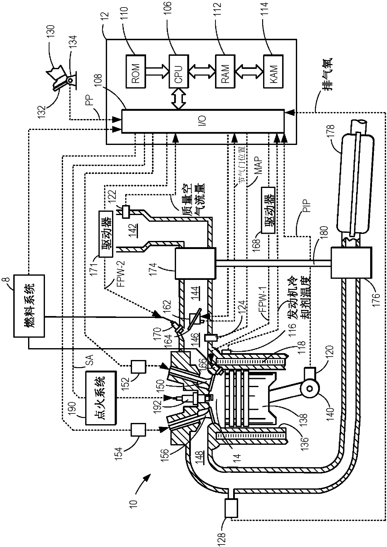
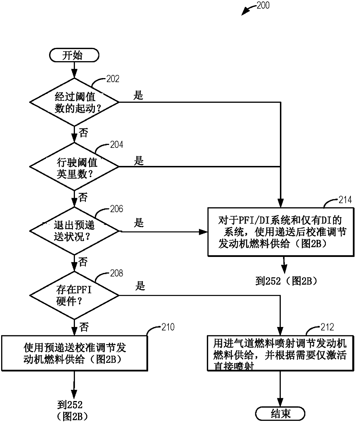
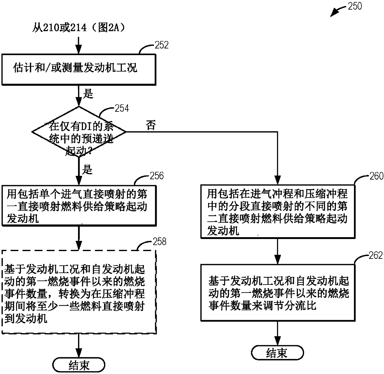
[0012] The following description relates to methods for adjusting fuel injection strategies to reduce such figure 1 Systems and methods for in-engine soot emissions in an engine system. The engine controller can be configured to execute control routines such as, Figure 2A An example routine of ) to determine a fueling strategy based on a single fueling capability or a dual fueling capability of an engine system. In engine systems that include port fuel injectors (PFI) and direct injectors (DI), while the vehicle is still in the assembly plant, the engine controller can fuel the engine with the PFI while intermittently enabling the DI, as Figure 2A shown. However, in engine systems that include only direct injectors, the engine controller may be configured to execute control routines such as, Figure 2B Example routine of ) to operate with a single intake stroke direct injection strategy during engine starts where there is a high propensity for spark plug fouling, such as ...


PUM


Abstract

Methods and systems are provided for controlling spark plug fouling in newly manufactured vehicles. In one example, a method may include operating an engine with a first direct injection fueling strategy including single intake direct injection on an engine start when in a pre-delivery state, and transitioning to a second different direct injection fueling strategy including split direct injectionon the engine start when in a post-delivery state. In this way, spark plug fouling may be avoided in newly manufactured vehicles.

Description

technical field [0001] The present description generally relates to methods and systems for fueling an engine of a vehicle after vehicle assembly. Background technique [0002] An engine ignition system may include a spark plug for delivering electrical current to a combustion chamber of a spark-ignition engine to ignite an air-fuel mixture and initiate combustion. Depending on engine operating conditions, spark plug fouling may occur, wherein the firing tip of the spark plug insulator becomes coated with foreign matter, such as fuel, oil, or soot. Once fouled, the spark plugs may not provide enough voltage to trigger cylinder combustion until the spark plugs are adequately cleaned or replaced. For example, spark plugs may be cleaned by operating the engine under speed-load conditions that sufficiently raise the temperature of the plug tip to burn off soot that has accumulated on a fouled spark plug. [0003] One example method for spark plug cleaning is shown by Glugla et...

Claims


Application Information

Patent Timeline
Patent Type & Authority Applications(China)
IPC IPC(8): F02D41/40F02D41/06
CPCF02D41/062F02D41/401F02D41/402F02D41/047F02D41/064F02D41/3094F02D2200/50F02B17/005F02D2041/389Y02T10/40F02D41/26
Inventor C·P·格卢格拉N·W·小莫如M·D·西泽卡拉G·J·胡伯茨易建文
Owner FORD GLOBAL TECH LLC
Learn More