
Workpiece locating and clamping equipment

A technology for clamping equipment and workpieces, which is applied to metal processing equipment, positioning devices, metal processing machinery parts, etc., and can solve problems such as unfastened clamping, affecting processing accuracy, and inability to stably clamp fixed chucks and fixed fixtures. , to achieve the effect of stable work, not easy to be blocked, and simple fixing method

Pending Publication Date: 2018-04-17
重庆朗奥机械有限公司
View PDF0 Cites 3 Cited by
  • Summary
  • Abstract
  • Description
  • Claims
  • Application Information

AI Technical Summary

Problems solved by technology

[0004] In view of the deficiencies in the prior art, the purpose of the present invention is to provide a workpiece positioning and clamping device, which solves the problem that the fixed chuck and the fixed fixture cannot be stably clamped during the processing of the shaft workpiece in the prior art, which leads to The clamping is not fastened, the workpiece rotates, and the technical problems that affect the machining accuracy

Method used


Image

  • Workpiece locating and clamping equipment
  • Workpiece locating and clamping equipment

Examples


Embodiment

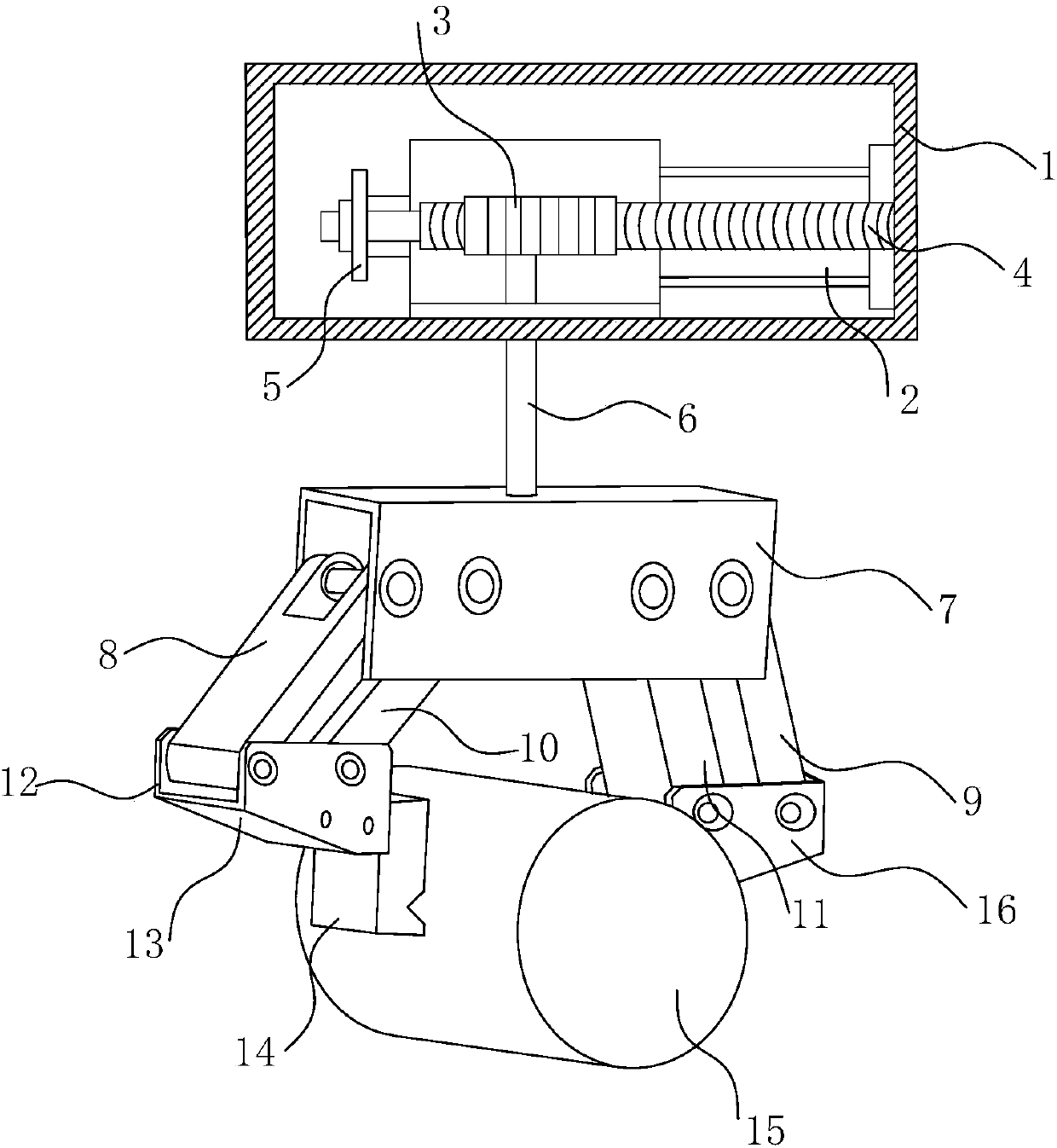
[0026] refer to Figure 1 ~ Figure 2 As shown: a workpiece positioning and clamping device, including a housing 1, the housing 1 is provided with an active driving mechanism, and also includes a driven driving mechanism driven by the active driving mechanism, and the driven driving mechanism drives the clamping Mechanism action; the active drive mechanism includes a cylinder 2, a drive rack 4 driven by the cylinder 2, and a drive gear 3 meshed with the drive rack 4; the cylinder 2 and the drive rack 4 are fixed on the connecting frame 5.

[0027] The driven drive mechanism includes a screw rod 6 connected to the driving gear 3, the first driven gear 17 and the second driven gear 18 are meshed on both sides of the screw rod 6 respectively; the driven drive mechanism is arranged in the fixed frame 7 , the screw rod 6 runs through the fixed frame 7 and is connected with the driving gear 3, and the fixed frame 7 is also provided with a left drive arm 10, a right drive arm 10 drive...


PUM


Abstract

The invention discloses workpiece locating and clamping equipment. The workpiece locating and clamping equipment comprises a shell, wherein an active drying mechanism is arranged in the shell, the workpiece locating and clamping equipment also comprises a slave driving mechanism driven by virtue of the active drying mechanism, and the slave driving mechanism drives a clamping mechanism to act; theactive drying mechanism comprises a cylinder, a driving rack driven by the cylinder and a driving gear meshed with the driving rack; the slave driving mechanism comprises a screw connected with the driving gear, and two sides of the screw are respectively meshed with a first driven gear and a second driven gear; the slave driving mechanism is arranged in a fixation frame, the screw runs through the fixation frame to be connected with the driving gear, and a left driving arm and a right driving arm which are respectively driven by the first driven gear and the second driven gear by virtue of the screw; and the cylinder drives the driving rack to drive the driving gear to move and drive the screw to rotate, so as to drive the left driving arm and the right driving arm to drive a left grabbing arm and a right grabbing arm, and the left grabbing arm and the right grabbing arm drive a left gripper and a right gripper to clamp or loosen.

Description

technical field [0001] The invention relates to a clamping device, in particular to a workpiece positioning and clamping device. Background technique [0002] In the process of workpiece processing, the workpiece needs to be clamped and fixed to ensure the stability of the workpiece during processing and improve the processing accuracy of the workpiece. Generally, a variety of fixed chucks and fixed fixtures are provided in the workpiece processing. [0003] However, during the processing of shaft workpieces, due to the arc-shaped forming surface, traditional fixed chucks or fixtures cannot achieve stable clamping of shaft workpieces, resulting in the workpiece being damaged due to loose clamping during processing. Problems such as rotation occur, which seriously affect the machining accuracy of the workpiece. Contents of the invention [0004] In view of the deficiencies in the prior art, the purpose of the present invention is to provide a workpiece positioning and clam...

Claims


Application Information

Patent Timeline
IPC IPC(8): B23Q3/00
CPCB23Q3/00B23Q2703/04B23Q2703/10
Inventor 陈东陈庆陈荣
Owner 重庆朗奥机械有限公司
Learn More