
Method for allocating transmit power in a wireless communication system

a wireless communication system and wireless communication technology, applied in power management, radio transmission, electrical equipment, etc., can solve the problem of lessening the effect of average total transmit power, achieve the effect of optimizing reverse link capacity, reducing pilot transmit power, and reducing average total transmit power

Inactive Publication Date: 2008-02-28
LUCENT TECH INC
View PDF6 Cites 31 Cited by
  • Summary
  • Abstract
  • Description
  • Claims
  • Application Information

AI Technical Summary

Benefits of technology

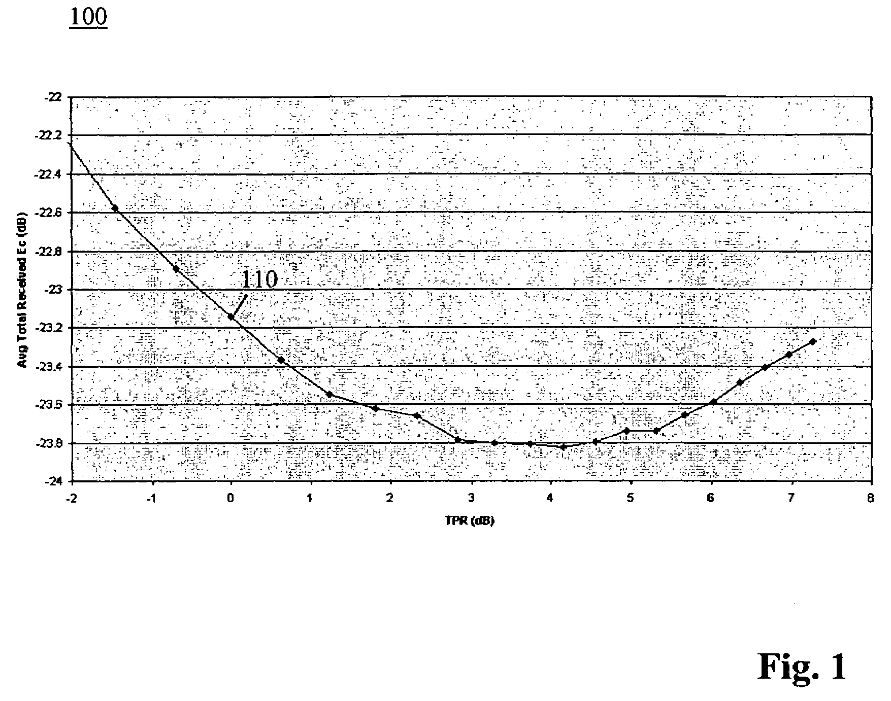
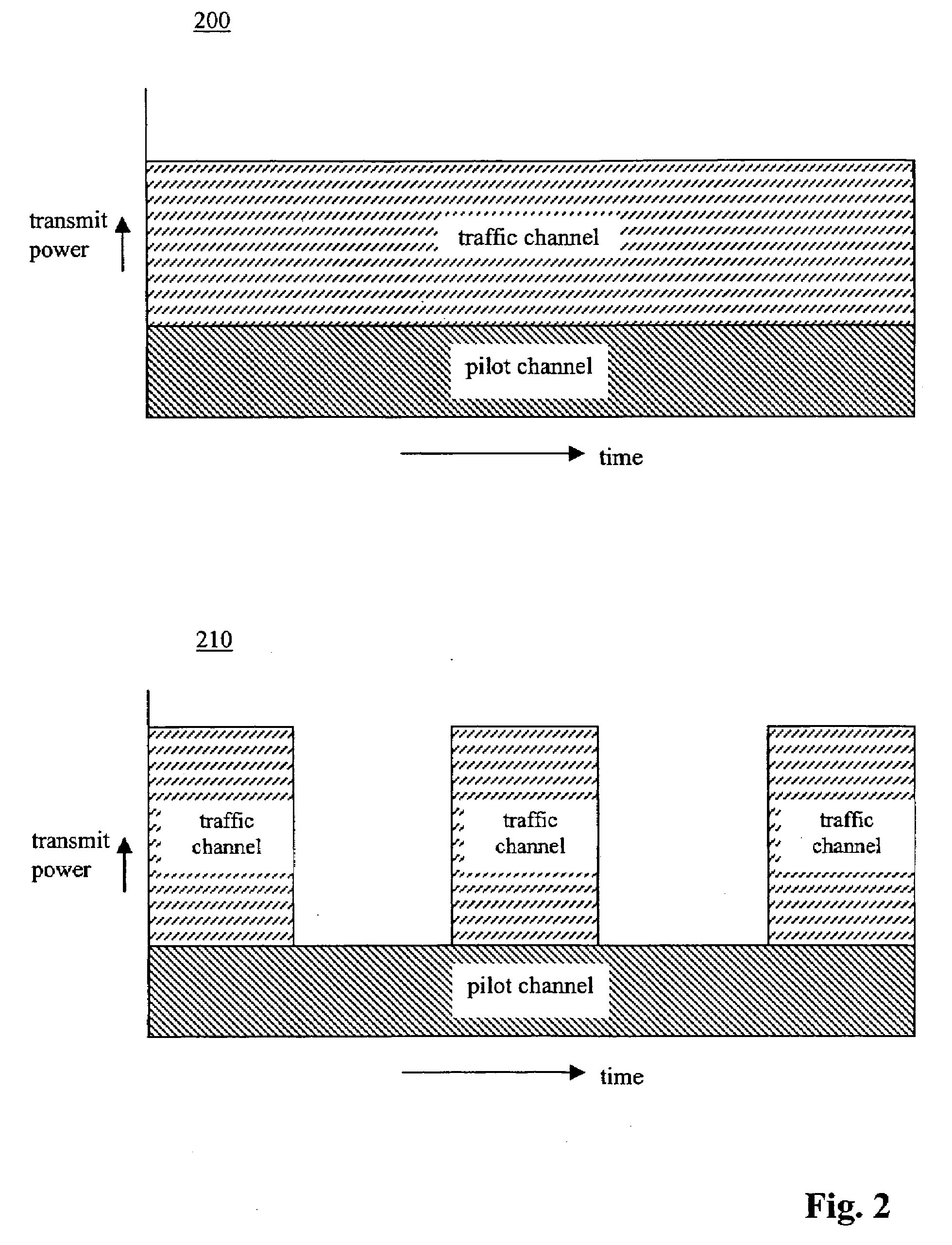
[0012]An embodiment of the present invention is a method for setting reverse link traffic and pilot transmit powers in a wireless communications system based on traffic channel activity in order to lower average total transmit power on the reverse link and optimize reverse link capacity. In accordance with one embodiment, as traffic channel activity decreases, a ratio between the traffic and pilot transmit powers, i.e., traffic-to-pilot ratio (TPR), should increase. Increasing TPR will produce lower pilot transmit powers and higher traffic transmit powers. Although higher traffic transmit powers are undesirable, the effect on average total transmit power is lessen because the traffic channel is not active all the time. By contrast, the pilot channel is always active and, thus, it may be desirable to sacrifice some performance of channel estimation in order to lower average total transmit power.

Problems solved by technology

Although higher traffic transmit powers are undesirable, the effect on average total transmit power is lessen because the traffic channel is not active all the time.

Method used


Image

  • Method for allocating transmit power in a wireless communication system
  • Method for allocating transmit power in a wireless communication system
  • Method for allocating transmit power in a wireless communication system

Examples


Embodiment Construction

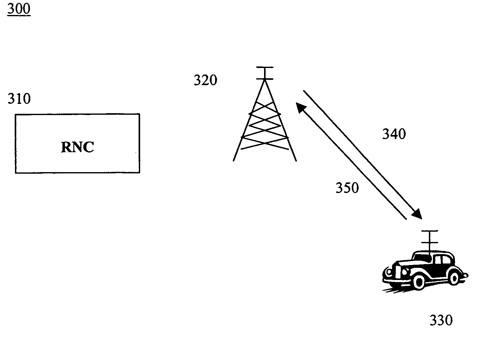
[0020]An embodiment of the present invention is a method of setting reverse link traffic and pilot transmit powers in a wireless communications system based on traffic channel activity in order to lower average total transmit power on the reverse link and optimize reverse link capacity. FIG. 3 depicts a wireless communication system 300 used in accordance with an embodiment of the present invention. Wireless communication system 300 can be, for example, a third generation (3G) wireless communication system based on Code Division Multiple Access (CDMA). Examples of such 3G systems include the well-known Universal Mobile Telecommunications System (UMTS) and CDMA2000 systems.

[0021]For illustration purposes, the present invention will be described herein with respect to voice applications in an UMTS system over a reverse link dedicated channel. It should be understood that the present invention may also be applicable to other types of applications, reverse or forward link shared channel...


PUM


Abstract

Disclosed is a method of setting reverse link traffic and pilot transmit powers in a wireless communications system based on traffic channel activity in order to lower average total transmit power on the reverse link and optimize reverse link capacity. As traffic channel activity decreases, the traffic transmit power relative to the pilot transmit power, i.e., traffic-to-pilot ratio (TPR), should increase. Increasing TPR will produce lower pilot transmit powers and higher traffic transmit powers. Although higher traffic transmit powers are undesirable, the effect on average total transmit power is lessen because the traffic channel is not active all the time. By contrast, the pilot channel is always active and, thus, it is desirable to sacrifice some performance of channel estimation in order to lower average total transmit power.

Description

FIELD OF THE INVENTION[0001]The present invention relates generally to wireless communication systems and, in particular, to setting reverse link transmit power in wireless communication systems.BACKGROUND OF THE INVENTION[0002]Optimizing reverse link capacity of third generation (3G) based wireless communication systems, such as Universal Mobile Telecommunications System (UMTS) and Code Division Multiple Access 2000 (CDMA2000) systems, involves minimizing total transmit power for each reverse link. Total transmit power includes transmit powers for a pilot channel and a traffic channel. The transmit power of the traffic channel relative to the pilot channel is referred to herein as a traffic-to-pilot ratio (TPR).[0003]The pilot transmit power is initially set based on a transmit power used by a mobile station to establish a connection with a base station over a random access channel (RACH). The initial pilot transmit power and a desired TPR are used to set the initial traffic transm...

Claims


Application Information

Patent Timeline
Patent Type & Authority Applications(United States)
IPC IPC(8): H04B7/00H04Q7/20H04W52/14H04W52/32
CPCH04W52/325H04W52/146
Inventor NAGARAJ, SHIRISHRAO, ANIL M.
Owner LUCENT TECH INC
Learn More