
Anti-vibrating optocoupler relay

An optocoupler relay and anti-vibration technology, applied in electrical components, electronic switches, pulse technology, etc., can solve problems such as poor heat dissipation, shock and vibration sensitivity, and small SSR isolation voltage

Inactive Publication Date: 2018-04-13
WUXI HAOBANG HIGH TECH CO LTD
View PDF5 Cites 0 Cited by
  • Summary
  • Abstract
  • Description
  • Claims
  • Application Information

AI Technical Summary

Problems solved by technology

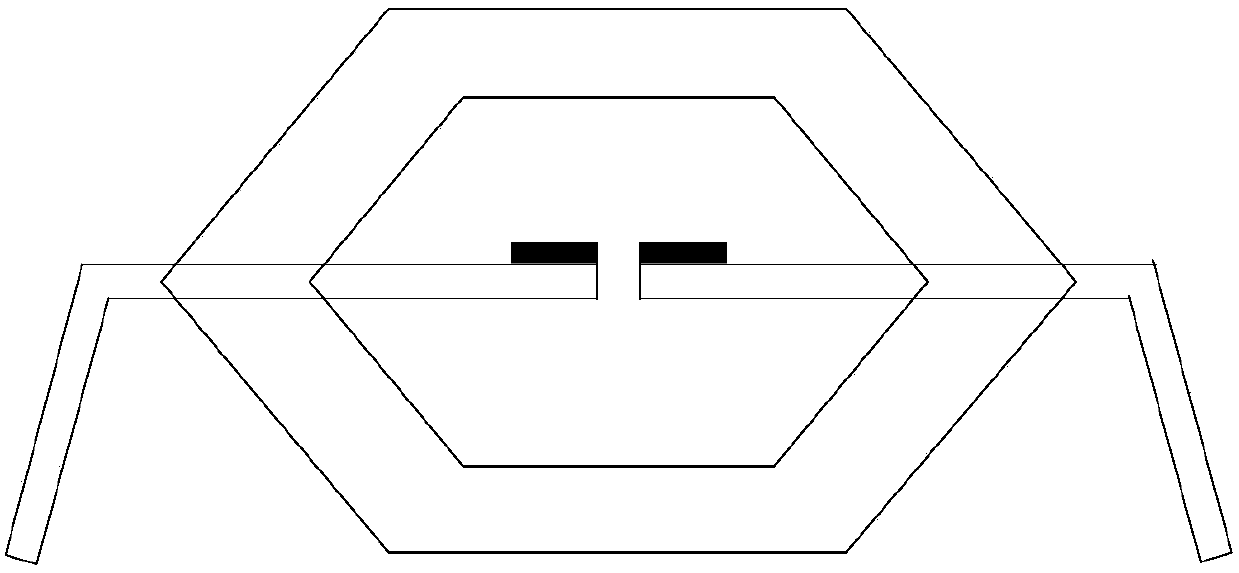
[0004] However, for the one-piece design, since it is a single-frame structure with only one layer of resin, it is easily deformed under external impact, so it is more sensitive to shock and vibration and has lower reliability; , in order to ensure that the signal receiving end can receive the signal transmitted by the signal sending end, usually the distance between the signal sending end and the signal receiving end is fixed at a small value, resulting in a small isolation voltage of the SSR; in addition, if the SSR application For motor control, due to the large parasitic inductance of the one-piece design, there will be a freewheeling effect after the mechanism stops, which will cause the problem that the current at the coil end continues to exist, and the heat dissipation effect is poor

Method used


Image

  • Anti-vibrating optocoupler relay
  • Anti-vibrating optocoupler relay
  • Anti-vibrating optocoupler relay

Examples


Embodiment Construction

[0030] The specific embodiments of the present invention will be further described below in conjunction with the accompanying drawings.

[0031] figure 2 It is a sectional view of an anti-vibration optocoupler relay provided by the present invention, such as figure 2 As shown, the optocoupler relay includes physically separated first frame 1 and second frame 2, the first frame 1 and the second frame 2 are placed in parallel in the horizontal direction of the section, and the first frame 1 and the second frame 2 are placed in the section partially overlap in the vertical direction.

[0032] The signal sending end 3 is arranged on the overlapping position on the first frame 1, and the signal receiving end 4 is arranged on the overlapping position on the second frame 2, and the signal sending end 3 is opposite to the signal receiving end 4 when assembling, and the signal sending end 3 It is physically isolated from the signal receiving end 4.

[0033] By physically separatin...


PUM

PropertyMeasurementUnit
Thicknessaaaaaaaaaa

Abstract

The invention discloses an anti-vibrating optocoupler relay, and relates to the technical field of the encapsulation. The optocoupler relay comprises a first frame and a second frame in physical separation; the first frame and the second frame are arranged in parallel in a horizontal direction of the section, and the first frame and the second frame are partially overlapped on a vertical directionof the section; a signal sending send is arranged on at overlapping location on the first frame, and a signal receiving end is arranged at the overlapping location on the second frame; the signal sending end and the signal receiving end are in face to face, and the signal sending end and the signal receiving end are in physical isolation,; the signal sending end and the signal receiving end are sealed in internal resin, and external resin are encapsulated at the external of the internal resin. The problem that the optocoupler relay is sensitive to vibration, low in reliability, small in isolation voltage, bad in radiating effect and has follow current due to the unibody design is solved, and the effects of buffering the impact of external force, improving the reliability, increasing the isolation voltage, avoiding the flow current influence and guaranteeing the radiation are achieved.

Description

technical field [0001] The invention relates to the technical field of packaging, in particular to an anti-vibration optocoupler relay. Background technique [0002] Most of the solid state relays (English: Solid State Relay, referred to as: SSR) use flame-retardant epoxy resin as the raw material, and adopt potting technology to isolate the SSR from the outside world. [0003] At present, SSR usually adopts one-piece design, and there is only one assembly frame, combined with reference figure 1 , The signal sending end and the signal receiving end are distributed left and right. When assembling, all the chips are assembled on the frame, pasted with silver paste, and then reflow soldered, the leads are connected, and the resin is fixed and aged for packaging. [0004] However, for the one-piece design, since it is a single-frame structure with only one layer of resin, it is easily deformed under external impact, so it is more sensitive to shock and vibration and has lower r...

Claims


Application Information

Patent Timeline
IPC IPC(8): H03K17/94
CPCH03K17/941H03K2217/941
Inventor 袁野袁瓅张国珠滕爱武
Owner WUXI HAOBANG HIGH TECH CO LTD
Learn More