Flowing path system

A flow path and flow path control technology, applied in the direction of biological testing, material inspection products, etc., can solve the problems of high user skill requirements, shortened electrode life, sensitive electrode influence, etc., to achieve increased life, less cross-contamination, and stable performance Effect

Pending Publication Date: 2018-04-13
SHENZHEN CORNLEY BIO MEDICAL CO LTD
View PDF0 Cites 2 Cited by
  • Summary
  • Abstract
  • Description
  • Claims
  • Application Information

AI Technical Summary

Problems solved by technology

Although the former has a certain effect on the cleaning of the flow path, it will also have a certain impact on the sensitive electrodes and shorten the life of the electrodes; the latter has no effect on the electrodes, but requires higher skills for the user and increases the labor intensity.

Method used


Image

  • Flowing path system

Examples


Embodiment 1

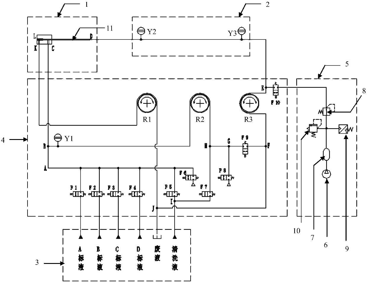
[0025] Such as figure 1 The shown flow path system includes a sampling part 1, a sample analysis part 2, a reagent part 3 and a flow path control part 4. The sampling part 1 is connected to the sample analysis part 2 and also includes a gas source forming part 5 connected to the flow path control part 4 .

[0026] The air source forming part 5 includes an air pump 6, an air storage tank 7 and a pressure reducing valve 8, and the air pump 6, the air storage tank 7 and the pressure reducing valve 8 are connected in sequence. Further, the gas source forming part 5 also includes a pressure sensor 9 and a safety valve 10 , and the pressure sensor 9 and the safety valve 10 are respectively connected to the gas storage tank 7 .

[0027] Further, the capacity of the air storage tank 7 is 1L, and the compressive strength is 0.7Mpa. The small-volume air storage tank can be easily installed inside the instrument without affecting the appearance of the instrument; the maximum pressure of...


PUM

PropertyMeasurementUnit
Compressive strengthaaaaaaaaaa

Abstract

The invention relates to a flowing path system, which is used for a blood gas electrolyte analysis instrument or an electrolyte analysis instrument. The flowing path system comprises a flowing path control part, a sampling part, a sample analysis part, a reagent part and a gas source forming part, wherein the sampling part, the sample analysis part, the reagent part and the gas source forming partare connected with the flowing path control part respectively; the sampling part is connected with the sample analysis part; the reagent part comprises a reagent bag and a waste liquid bag; a reagententers the flowing path system through the reagent bag, and flows into the waste liquid bag sequentially through the flowing path control part, the sampling part, the sample analysis part and the flowing path controlling part; the gas source forming part comprises a gas pump, a gas storage tank and a pressure reducing valve; compressed gas enters the gas storage tank through the gas pump; after the pressure reduction through the pressure reducing valve, the gas sequentially passes through the flowing path control part, the sample analysis part, the sampling part, the flowing path control partand the reagent part; residue reagents in the flowing path system are flushed to enter the waste liquid bag. The compressed gas is used for reverse flushing; most residue reagents in the flowing pathare cleanly flushed; the instrument has little crossed pollution during the measurement of a plurality of samples; the performance is more stable.

Description

technical field [0001] The invention relates to an electrolyte analyzer, in particular to a flow path system which can be used in a blood gas electrolyte analyzer or an electrolyte analyzer. Background technique [0002] At present, the performance of domestic blood gas and electrolyte analyzers tends to be stable, and the flow path design is becoming more and more mature, but it is also a common phenomenon that the flow path of medical instruments is not cleaned cleanly. The measures currently taken mainly include enhancing the cleaning ability of the cleaning solution, changing the flow path regularly, and artificially degreasing the instrument. Although the former has a certain effect on cleaning the flow path, it will also have a certain impact on sensitive electrodes and shorten the life of the electrodes; the latter has no effect on the electrodes, but requires higher skills for users and increases labor intensity. Contents of the invention [0003] The invention pr...

Claims


Application Information

Patent Timeline
IPC IPC(8): G01N33/48
CPCG01N33/48
Inventor 黄伟房广志
Owner SHENZHEN CORNLEY BIO MEDICAL CO LTD
Why Eureka
Try Eureka